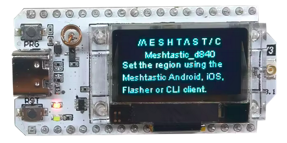
Dans un précédent tutoriel, je vous présentais Meshtastic, une solution pour créer des réseaux maillés décentralisés et autonomes. La brique élémentaire de ce réseau est le nœud, généralement composé d’un microcontrôleur, d’une puce radio LoRa et d’une antenne.
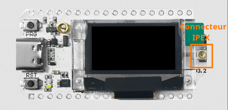
Cependant, la connexion entre la carte et l’antenne mérite une attention particulière. De nombreux modules utilisent des connecteurs de type IPEX (ou U.FL). S’ils ont l’avantage d’être compacts, ces connecteurs sont relativement fragiles et n’offrent pas toujours une liaison parfaitement fiable. Il arrive ainsi que l’antenne soit déconnectée sans que l’utilisateur s’en rende compte.
Cette situation n’est pas anodine. Sur certains forums, des utilisateurs rapportent qu’émettre sans antenne peut, dans certaines conditions, endommager l’amplificateur de puissance (PA) du module radio, voire le rendre inutilisable.
Pour vous éviter toute inquiétude — ou pour diagnostiquer un comportement suspect — j’ai conçu un petit programme de test simple et efficace. Il permet de vérifier rapidement la chaîne complète d’émission et de réception d’un nœud Heltec V3 (avec une adaptation possible à d’autres modules LoRa).
Le principe est très simple, mais nécessite deux modules Heltec V3 :
- Le premier module envoie des trames à différentes puissances d’émission.
- Le second module les reçoit et affiche la puissance reçue (RSSI) et le rapport signal/bruit (SNR).
Ce test vous permettra de valider le bon fonctionnement de vos cartes et de vous assurer que leur amplificateur de puissance fonctionne correctement.
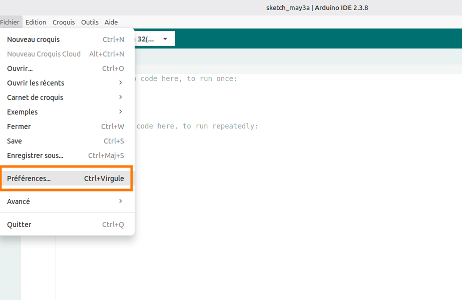
Pour ce tutoriel, j’ai choisi l’IDE Arduino : un environnement accessible à tous, même sans compétences avancées en programmation.
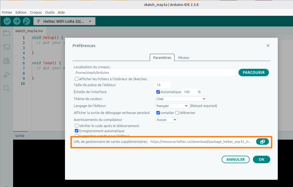
Installation du gestionnaire de carte Heltec ESP32
Ajouter l’URL https://resource.heltec.cn/download/package_heltec_esp32_index.json à la liste des gestionnaires de cartes supplémentaires :
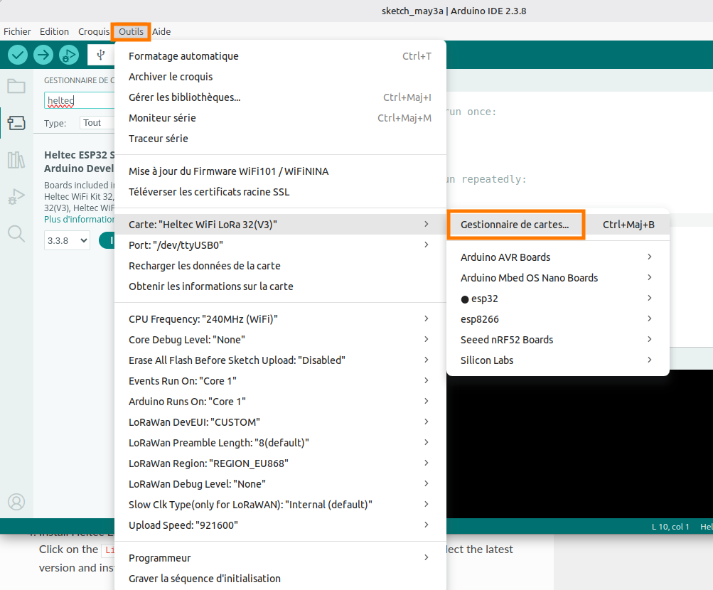
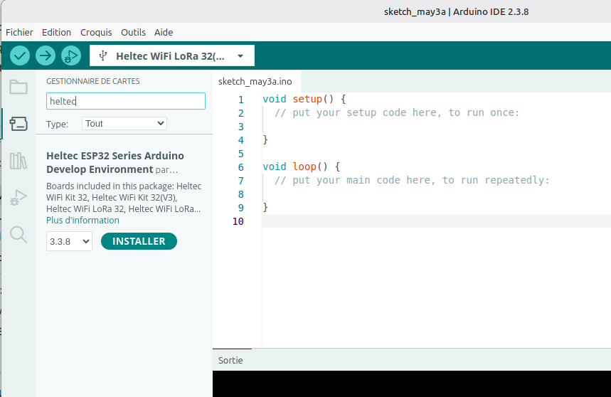
Et installer le gestionnaire de cartes Heltec ESP32 Series Arduino Develop Environment par Heltec Automation :
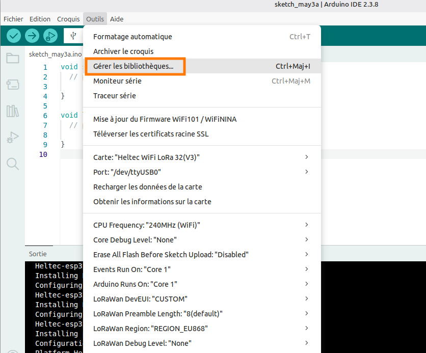
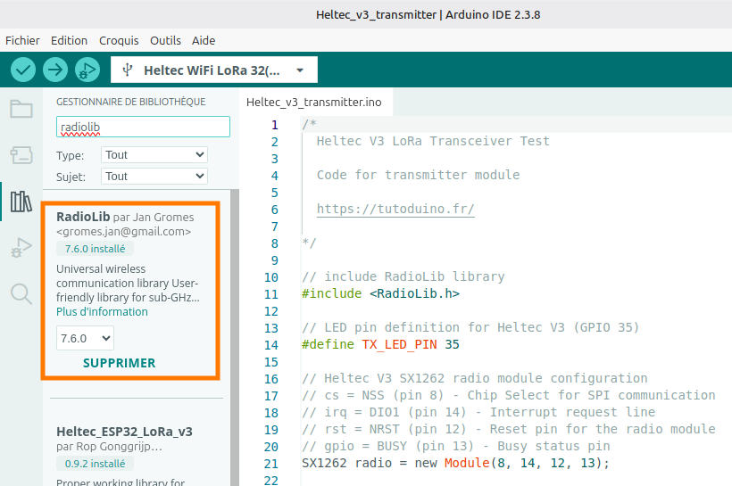
Installation de la librairie RadioLib
La librairie RadioLib par Jan Gromes est une bibliothèque de communication sans fil universelle pour différents microcontrôleurs qui supporte une grande variété de modules radio (SX1262, SX127x, RF69, CC1101, nRF24L01, etc.) et permet d’utiliser facilement le protocole LoRa.
Le programme
Comme je l’ai indiqué plus haut, le principe du test est très simple, mais nécessite deux modules Heltec V3. Le premier module envoie des trames à différentes puissances d’émission (-2 dBm, 5 dBm et 10 dBm) alors que le second module les reçoit et affiche la puissance reçue (RSSI) et le rapport signal/bruit (SNR).
Afin de simplifier la compréhension, j’ai décidé de fournir deux codes différents. Un pour le module émetteur, un autre pour le module récepteur.
Voici le code pour le module Heltec V3 en mode émetteur LoRa :
/*
  Heltec V3 LoRa Transceiver Test

  Code for transmitter module

  https://tutoduino.fr/

*/

// include RadioLib library
#include <RadioLib.h>

// LED pin definition for Heltec V3 (GPIO 35)
#define TX_LED_PIN 35
#define USER_BUTTON 0

// Heltec V3 SX1262 radio module configuration
// cs = NSS (pin 8) - Chip Select for SPI communication
// irq = DIO1 (pin 14) - Interrupt request line
// rst = NRST (pin 12) - Reset pin for the radio module
// gpio = BUSY (pin 13) - Busy status pin
SX1262 radio = new Module(8, 14, 12, 13);

// Flag to indicate that packet sending is completed
// Volatile because it's modified inside an interrupt handler (setFlag)
volatile bool packetSendingCompleted = false;

// Store transmission state between loop iterations
// Values can be RADIOLIB_ERR_NONE (success) or error codes
int transmissionState = RADIOLIB_ERR_NONE;

// State machine enumeration for tracking transmission sequence
enum State {
  INIT_STATE,                // Initial state, ready to send first packet
  FIRST_PACKET_SENT_STATE,   // First packet sent, waiting for completion
  SECOND_PACKET_SENT_STATE,  // Second packet sent, waiting for completion
  THIRD_PACKET_SENT_STATE    // Third packet sent, waiting for completion
};

// Current state of the transmitter state machine
State state;

// Interrupt Service Routine (ISR) called when packet transmission completes
// This function is triggered by the DIO1 pin interrupt
void setFlag(void) {
  // Packet was sent successfully, set the flag for the main loop
  packetSendingCompleted = true;
  // Turn off the transmission LED to indicate transmission is complete
  digitalWrite(TX_LED_PIN, LOW);
}

void setup() {
  // Initialize serial communication for debug output
  Serial.begin(115200);
  delay(1000);  // Allow serial to stabilize

  Serial.println("Heltec V3 LoRa Transceiver Test - Transmitter module");
  Serial.print("ChipId = ");
  Serial.println(ESP.getEfuseMac());

  // Configure the transmission LED pin
  pinMode(TX_LED_PIN, OUTPUT);
  digitalWrite(TX_LED_PIN, LOW);  // Ensure LED starts in OFF state

  pinMode(USER_BUTTON, INPUT);

  // Initialize SX1262 radio module
  float frequency = 869.4;
  float bandwidth = 125.0;
  uint8_t spreadingFactor = 9;
  uint8_t codingRate = 5;
  uint8_t syncWord = 0x12;
  int8_t power = -2;
  uint16_t preambleLength = 8;
  int rc = radio.begin(frequency, bandwidth, spreadingFactor, codingRate, syncWord, power, preambleLength);
  if (rc == RADIOLIB_ERR_NONE) {
    Serial.println(F("SX1262 init success!"));
  } else {
    Serial.print(F("SX1262 init failed, code "));
    Serial.println(rc);          // Print error code for debugging
    while (true) { delay(10); }  // Halt execution on failure
  }

  // Register the interrupt handler function
  // This will be called automatically when DIO1 pin triggers
  radio.setDio1Action(setFlag);

  // Initialize state machine to starting state
  state = INIT_STATE;
}

void loop() {
  // State machine handles the sequential transmission of 3 packets
  switch (state) {
    case INIT_STATE:
      // Wait user button push to start sending packets
      Serial.println("Push PRG button to start test");
      while (digitalRead(USER_BUTTON) == HIGH) {
        delay(10);
      }

      Serial.println("Start sending packets...");

      // Prepare and send first packet at very low power (-9 dBm)
      digitalWrite(TX_LED_PIN, HIGH);  // Turn LED ON before transmission
      Serial.println("Sending packet at -9 dBm \tPacket data: \"Packet #1 at -9 dBm\"");
      radio.setOutputPower(-9);  // Very low power for close-range testing
      transmissionState = radio.startTransmit("Packet #1 at -9 dBm");
      state = FIRST_PACKET_SENT_STATE;
      // IMPORTANT: No delay here - we wait for interrupt to continue
      break;

    case FIRST_PACKET_SENT_STATE:
      // Wait for the previous transmission to complete
      if (packetSendingCompleted) {
        // Reset flag for next transmission
        packetSendingCompleted = false;

        // Check if transmission was successful
        if (transmissionState != RADIOLIB_ERR_NONE) {
          Serial.print("Packet #1 sending failed, code ");
          Serial.println(transmissionState);
        }

        // Prepare and send second packet at low power (5 dBm)
        digitalWrite(TX_LED_PIN, HIGH);  // Turn LED ON for next transmission
        Serial.println("Sending packet at 0 dBm \tPacket data: \"Packet #2 at 0 dBm\"");
        radio.setOutputPower(0);  // Low power
        transmissionState = radio.startTransmit("Packet #2 at 0 dBm");
        state = SECOND_PACKET_SENT_STATE;
        // No delay - wait for interrupt notification
      }
      break;

    case SECOND_PACKET_SENT_STATE:
      // Wait for the previous transmission to complete
      if (packetSendingCompleted) {
        // Reset flag for next transmission
        packetSendingCompleted = false;

        // Check if transmission was successful
        if (transmissionState != RADIOLIB_ERR_NONE) {
          Serial.print("Packet #2 sending failed, code ");
          Serial.println(transmissionState);
        }

        // Prepare and send third packet at medium power (5 dBm)
        digitalWrite(TX_LED_PIN, HIGH);  // Turn LED ON for next transmission
        Serial.println("Sending packet at 5 dBm \tPacket data: \"Packet #3 at 5 dBm\"");
        radio.setOutputPower(5);  // Medium power for better range
        transmissionState = radio.startTransmit("Packet #3 at 5 dBm");
        state = THIRD_PACKET_SENT_STATE;
        // No delay - wait for interrupt notification
      }
      break;

    case THIRD_PACKET_SENT_STATE:
      // Wait for the previous transmission to complete
      if (packetSendingCompleted) {
        // Reset flag for next transmission
        packetSendingCompleted = false;

        // Check if transmission was successful
        if (transmissionState != RADIOLIB_ERR_NONE) {
          Serial.print("Packet #3 sending failed, code ");
          Serial.println(transmissionState);
        }

        // Wait 5 seconds before starting the entire sequence again
        // This gives the receiver time to process and display packets
        delay(5000);
        state = INIT_STATE;  // Reset to beginning
      }
      break;

    default:
      // Fallback handler for unexpected states
      delay(5000);
      state = INIT_STATE;
      break;
  }
}
Voici le code pour le module Heltec V3 en mode récepteur LoRa :
/*
  Heltec V3 LoRa Transceiver Test

  Code for receiver module

  https://tutoduino.fr/

*/

// Include the RadioLib library for LoRa communication
#include <RadioLib.h>

// Heltec V3 SX1262 radio module configuration
// cs = NSS (pin 8) - Chip Select for SPI communication
// irq = DIO1 (pin 14) - Interrupt request line (signals packet received)
// rst = NRST (pin 12) - Reset pin for the radio module
// gpio = BUSY (pin 13) - Busy status pin (indicates radio operation)
SX1262 radio = new Module(8, 14, 12, 13);

// Flag to indicate that a packet was received
// Volatile because it's modified inside an interrupt handler (setFlag)
// and read in the main loop (prevents compiler optimization)
volatile bool operationDone = false;

// Interrupt Service Routine (ISR)
// This function is automatically called when a complete packet
// is received by the module (triggered by DIO1 pin interrupt)
void setFlag(void) {
  // A packet was received, set the flag for the main loop to process
  // Keep this function as short as possible (no Serial.print here!)
  operationDone = true;
}

void setup() {
  // Variable to store return codes from RadioLib functions
  // Typical values: RADIOLIB_ERR_NONE (0) = success, negative = error
  int rc;

  // Initialize serial communication for debug output
  Serial.begin(115200);
  delay(1000);  // Allow serial connection to stabilize

  // Print program header information
  Serial.println("Heltec V3 LoRa Transceiver Test - Receiver module");
  Serial.print("ChipId = ");
  Serial.println(ESP.getEfuseMac());

  // --------------------------------------------------------------------
  // RADIO INITIALIZATION
  // --------------------------------------------------------------------

  // Initialize SX1262 radio module
  float frequency = 869.4;
  float bandwidth = 125.0;
  uint8_t spreadingFactor = 9;
  uint8_t codingRate = 5;
  uint8_t syncWord = 0x12;
  int8_t power = -2;
  uint16_t preambleLength = 8;
  rc = radio.begin(frequency, bandwidth, spreadingFactor, codingRate, syncWord, power, preambleLength);
  if (rc == RADIOLIB_ERR_NONE) {
    Serial.println("SX1262 init success!");
  } else {
    // Initialization failed - print error code and halt execution
    Serial.print("SX1262 init failed, code ");
    Serial.println(rc);
    while (true) { delay(10); }  // Infinite loop stops program here
  }

  // Register the interrupt handler function with the radio module
  // The setFlag() function will be called automatically when DIO1 pin
  // triggers (i.e., when a packet is fully received)
  radio.setDio1Action(setFlag);

  // --------------------------------------------------------------------
  // START RECEPTION
  // --------------------------------------------------------------------

  // Start listening for LoRa packets in continuous receive mode
  // The radio stays in receive mode and generates an interrupt
  // whenever a complete packet arrives
  Serial.println("Ready to receive packets...");
  rc = radio.startReceive();
  if (rc != RADIOLIB_ERR_NONE) {
    // Failed to start reception - print error and halt
    Serial.print("startReceive failed, code ");
    Serial.println(rc);
    while (true) { delay(10); }
  }
  // Note: No need to restart receive here - radio stays in receive mode
  // automatically after startReceive() is called once
}

void loop() {
  // Check if a packet was received (flag set by interrupt)
  if (operationDone) {
    // Reset flag immediately to avoid missing subsequent packets
    // Must be done before processing to prevent race conditions
    operationDone = false;

    // Buffer to store the received packet data as a String
    String str;

    // Read the received packet data from the radio
    // The data is copied into the 'str' variable
    int rc = radio.readData(str);

    if (rc == RADIOLIB_ERR_NONE) {
      // ----------------------------------------------------------------
      // SUCCESSFUL PACKET RECEPTION
      // ----------------------------------------------------------------

      Serial.print("Packet received");

      // Print RSSI (Received Signal Strength Indicator)
      // Typical range: -30 dBm (very strong) to -120 dBm (very weak)
      // "\t" adds a tab character for formatted column alignment
      Serial.print("\tRSSI: ");
      Serial.print(radio.getRSSI());
      Serial.print(" dBm");

      // Print SNR (Signal-to-Noise Ratio)
      // Positive values = signal stronger than noise
      // LoRa can decode with SNR as low as -20 dB (high spreading factor)
      Serial.print("\tSNR: ");
      Serial.print(radio.getSNR());
      Serial.print(" dB");

      // Print the actual packet data content, enclosed in quotes
      // The \" escapes the double quotes in the output
      Serial.print("\tPacket data: \"");
      Serial.print(str);
      Serial.println("\"");  // println adds newline after closing quote

      // CRITICAL: Restart reception for the next packet
      // After readData(), the radio automatically exits receive mode
      // Must explicitly restart to listen for more packets
      radio.startReceive();

    } else {
      // ----------------------------------------------------------------
      // RECEPTION ERROR HANDLING
      // ----------------------------------------------------------------
      // Possible errors:
      // - RADIOLIB_ERR_RX_TIMEOUT: No packet received within timeout
      // - RADIOLIB_ERR_CRC_MISMATCH: Packet corrupted (CRC check failed)
      // - Other negative codes for various hardware errors

      Serial.print("Reception failed, code ");
      Serial.println(rc);

      // Attempt to restart reception despite the error
      // This keeps the radio listening for future packets
      radio.startReceive();
    }
  }
  // If operationDone == false, do nothing and loop again
  // The CPU is free to do other tasks while waiting for packets
}
Résultats du test
Voici un exemple de traces observées dans le moniteur série. Ces résultats confirment le bon fonctionnement des deux modules. Pour une validation complète, je vous recommande d’inverser leurs rôles et de vérifier que les mesures sont similaires. Vous testerez ainsi l’intégralité de la chaîne d’émission et de réception LoRa sur les deux cartes.
Heltec V3 LoRa Transceiver Test - Transmitter module
SX1262 init success!
Start sending packets...
Sending packet at -2 dBm 	Packet data: "Packet #1 at -2 dBm"
Sending packet at 5 dBm 	Packet data: "Packet #2 at 5 dBm"
Sending packet at 10 dBm 	Packet data: "Packet #3 at 10 dBm"
Heltec V3 LoRa Transceiver Test - Receiver module
SX1262 init success!
Start receiving packets...
Packet received RSSI: -63.00 dBm SNR: 11.00 dB Packet data: "Packet #1 at -2 dBm"
Packet received RSSI: -56.00 dBm SNR: 11.50 dB Packet data: "Packet #2 at 5 dBm"
Packet received RSSI: -52.00 dBm SNR: 10.75 dB Packet data: "Packet #3 at 10 dBm"Interprétation de ces résultats
Il faut déjà noter que les trois paquets sont envoyés et reçus sans erreur. Ce qui signifie que la chaîne complète (émission → réception) est opérationnelle.
Le RSSI augmente avec la puissance émise, ce qui signifie que le PA (amplificateur d’émission) répond correctement aux réglages et qu’il n’est pas endommagé (sa réponse est bien calibrée).
Le SNR est stable autour de 10-11 dB, indiquant que le LNA (amplificateur de réception) a un gain linéaire et le bruit de fond est faible.
L’atténuation constante d’environ 61-62 dB est parfaitement normale et s’explique par la perte en espace libre à 1 mètre (32 dB) et probablement le rendement des antennes (25 dB au mieux).
Note : Les modules Heltec V3, équipés du chip SX1262, intègrent un mécanisme de protection de l’amplificateur de puissance (PA) en cas de désadaptation d’antenne (y compris une antenne déconnectée). Ce circuit, appelé « PA clamping », détecte les surtensions internes causées par une mauvaise adaptation et réduit automatiquement la puissance de sortie du PA afin de protéger les composants internes et garantir la fiabilité à long terme du chip.