
Want to analyze your ESP32 WiFi performance? Measure available Wi-Fi networks and signal strength, then benchmark real-world TCP throughput. This tutorial provides both network scanning and download speed testing for your ESP32 projects.
Part 1: Wi-Fi signal strength
The first part of this tutorial is a basic Wi-Fi network scan, to measure available Wi-Fi networks and signal strength. Signal strength is measured by the RSSI (Received Signal Strength Indicator), which is the power level of a received Wi-Fi signal in dBm (decibels relative to 1 milliwatt).
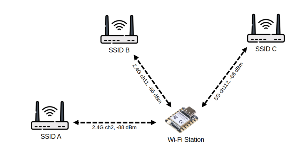
The code below scans both 2.4 GHz and 5 GHz networks, displaying channel numbers and RSSI for each found network. The ESP32 then connects to your WiFi and continuously monitors RSSI—ideal for testing signal range or verifying antenna reception quality (gain)
//
// ESP32 WiFi test program
// https://tutoduino.fr/
//
#include <WiFi.h>      // WiFi library for ESP32
#include <esp_wifi.h>  // ESP-IDF WiFi control functions
#include "secret.h"    // Contains WIFI_SSID and WIFI_PASSWORD definitions
void setup() {
  Serial.begin(115200);  // Initialize serial communication
  delay(1000);           // Small startup delay
  Serial.println("ESP32 WiFi Test - Tutoduino");
  scanWifi();       // Scan nearby 2.4GHz and 5GHz networks
  connectToWifi();  // Try to connect to your WiFi network
}
void loop() {
  // Check if the device is still connected to the WiFi network
  if (WiFi.status() == WL_CONNECTED) {
    int ch = WiFi.channel();   // Get current WiFi channel
    bool is5GHz = (ch >= 36);  // Channels 36+ correspond to 5GHz
    // Print IP address and signal info
    Serial.printf("Connected with IP: %s\n", WiFi.localIP().toString().c_str());
    Serial.printf("Channel: %d (%s GHz) | RSSI: %d dBm\n",
                  ch, is5GHz ? "5" : "2.4", WiFi.RSSI());
  } else {
    // If disconnected, try to reconnect automatically
    Serial.println("Disconnected, trying to reconnect...");
    WiFi.reconnect();
  }
  delay(5000);  // Wait before repeating the loop
}
void scanWifi() {
  int n;
  esp_err_t err;
  WiFi.mode(WIFI_STA);  // Set WiFi to station (client) mode
  // ----------- 5 GHz scan -----------
  Serial.println("Scanning 5 GHz WiFi networks...");
  err = esp_wifi_set_band_mode(WIFI_BAND_MODE_5G_ONLY);  // Restrict to 5 GHz
  if (err != ESP_OK) {
    Serial.println("Set 5G band failed!");
  }
  n = WiFi.scanNetworks();  // Perform the 5GHz scan
  for (int i = 0; i < n; ++i) {
    int ch = WiFi.channel(i);
    if (ch >= 36) {
      Serial.printf("[%d] %s (5G ch%d, %d dBm)\n",
                    i + 1, WiFi.SSID(i).c_str(), ch, WiFi.RSSI(i));
    } else {
      Serial.printf("[%d] %s (2.4G ch%d, %d dBm)\n",
                    i + 1, WiFi.SSID(i).c_str(), ch, WiFi.RSSI(i));
    }
  }
  WiFi.scanDelete();
  // ----------- 2.4 GHz scan -----------
  Serial.println("Scanning 2.4 GHz WiFi networks...");
  err = esp_wifi_set_band_mode(WIFI_BAND_MODE_2G_ONLY);  // Restrict to 2.4 GHz
  if (err != ESP_OK) {
    Serial.println("Set 2G band failed!");
  }
  n = WiFi.scanNetworks();  // Perform network scan
  for (int i = 0; i < n; ++i) {
    int ch = WiFi.channel(i);
    // Display basic info for each found network
    if (ch >= 36) {
      Serial.printf("[%d] %s (5G ch%d, %d dBm)\n",
                    i + 1, WiFi.SSID(i).c_str(), ch, WiFi.RSSI(i));
    } else {
      Serial.printf("[%d] %s (2.4G ch%d, %d dBm)\n",
                    i + 1, WiFi.SSID(i).c_str(), ch, WiFi.RSSI(i));
    }
  }
  WiFi.scanDelete();  // Free memory from scan results
}
// Function to connect the ESP32 to the provided WiFi network
void connectToWifi() {
  Serial.printf("Connecting to %s...\n", WIFI_SSID);
  WiFi.mode(WIFI_STA);                   // Set WiFi to station (client) mode
  WiFi.begin(WIFI_SSID, WIFI_PASSWORD);  // Start connection with credentials
  int attempts = 0;
  // Wait up to 20 attempts (about 10 seconds total)
  while (WiFi.status() != WL_CONNECTED && attempts < 20) {
    delay(500);
    Serial.print(".");
    attempts++;
  }
  // Report connection result
  Serial.println(WiFi.status() == WL_CONNECTED ? "\nConnected!" : "\nFailed to connect");
}Example of output on Arduino IDE Serial Monitor showing2.4G and 5G Wi-Fi networks. The ESP32-C6 then connect to my Wi-Fi and display channel and RSSI:
17:30:34.782 -> ESP32 WiFi Test - Tutoduino
17:30:35.393 -> Scanning 5 GHz WiFi networks...
17:30:42.356 -> [1] MyWifi_5GHz (5G ch112, -68 dBm)
17:30:42.356 -> Scanning 2.4 GHz WiFi networks...
17:30:45.372 -> [1] MyWifi (2.4G ch11, -70 dBm)
17:30:45.372 -> [2] Freebox-0265C0 (2.4G ch6, -84 dBm)
17:30:45.372 -> [3] Maison Cabanon (2.4G ch2, -88 dBm)
17:30:45.372 -> [4] Jiggabox (2.4G ch6, -88 dBm)
17:30:45.372 -> [5] Jiggabox-invité (2.4G ch6, -89 dBm)
17:30:45.372 -> [6] Livebox-20B0 (2.4G ch6, -89 dBm)
17:30:45.372 -> [7] Livebox-30E0 (2.4G ch1, -91 dBm)
17:30:45.372 -> [8] WIFI7-YOU (2.4G ch1, -93 dBm)
17:30:45.372 -> [9] boxjack02 (2.4G ch2, -95 dBm)
17:30:45.372 -> [10] wifiRoom (2.4G ch6, -95 dBm)
17:30:45.372 -> Connecting to MyWifi...
17:30:45.885 -> ...
17:30:46.880 -> Connected!
17:30:46.880 -> Connected with IP: 192.168.1.31
17:30:46.880 -> Channel: 11 (2.4 GHz) | RSSI: -68 dBm
17:30:51.890 -> Connected with IP: 192.168.1.31
17:30:51.890 -> Channel: 11 (2.4 GHz) | RSSI: -69 dBm
17:30:56.875 -> Connected with IP: 192.168.1.31
17:30:56.875 -> Channel: 11 (2.4 GHz) | RSSI: -59 dBm
17:31:01.875 -> Connected with IP: 192.168.1.31
17:31:01.875 -> Channel: 11 (2.4 GHz) | RSSI: -59 dBmThis example demonstrates the impact of upgrading to a higher-gain antenna on signal reception strength. At 17:30:56, replacing the antenna boosts the RSSI from −69 dBm to −59 dBm, reflecting a markedly stronger received signal.
Part 2: Wi-Fi throughput
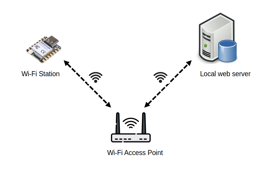
In this test, we measure Wi-Fi throughput on ESP32 by transferring a 20 MB file from a local Linux web server to your ESP32.
Before going further, I remind you some concepts for the units of information:
- Bit (b) → most basic unit of information (0 or 1)
- Kilobit (kb ou kbit) → 1 kbit = 1 000 b
- Megabit (Mb ou Mbit) → 1 Mbit = 1 000 000 b
- Byte (B) → 1 B = 8 b
- Kilobyte (kB) → 1 kB = 1 000 B
- Kibibyte (KiB) → 1 KiB = 1 024 B
- Megabyte (MB) → 1 MB = 1 000 x 1 000 B = 1 000 000 B
- Mebibyte (MiB) → 1 MiB = 1 024 x 1 024 B = 1 048 576 B
1. Server Setup (Linux)
Create 20 MiB (Mebibyte) random data file with this command on the local Linux server:
dd count=20480 bs=1024 if=/dev/random of=/tmp/data20 480 blocks × 1 024 bytes/block = 20,971,520 bytes = 20 × 1 048 576 bytes = 20 MiB = ~21 MB.
2. HTTP server
Start a simple Python HTTP server with this command executed on the local Linux server:
python3 -m http.server 8080 -d /tmpYou can test that local web server is operational with this command executed on the local Linux server:
tutoduino@F15:~$ curl -o /dev/null http://127.0.0.1:8080/data
  % Total    % Received % Xferd  Average Speed   Time    Time     Time  Current
                                 Dload  Upload   Total   Spent    Left  Speed
100 20.0M  100 20.0M    0     0  2428M      0 --:--:-- --:--:-- --:--:-- 2500M
3. ESP32 Client with Arduino IDE
The Arduino IDE provides an accessible entry point for ESP32 development, yet it yields reduced Wi-Fi performance compared to ESP-IDF’s native optimizations. Let us start with basic measurement with Arduino IDE.
Compile and upload this code to your ESP32. It performs HTTP GET requests from ESP32 to download the 21 MB file from the local web server and calculates Wi-Fi throughput in Mbit/s.
//
// ESP32 Wi-Fi throughput test program
//
// https://tutoduino.fr/
//
#include <WiFi.h>
#include "secret.h"    // Contains WIFI_SSID and WIFI_PASSWORD definitions
// Global TCP client object
WiFiClient client;
void setup() {
  esp_err_t err;
  // Start serial console for debug output
  Serial.begin(115200);
  delay(1000);
  Serial.println("ESP32 WiFi Throughput Test - Tutoduino");
  // Connect to WiFi access point
  Serial.println("Connecting to WiFi...");
  WiFi.mode(WIFI_STA);
  WiFi.begin(WIFI_SSID, WIFI_PASSWORD);
  // Wait until connected (blocking loop)
  while (WiFi.status() != WL_CONNECTED) {
    delay(500);
    Serial.print(".");
  }
  Serial.println();
  Serial.println("WiFi connected!");
  Serial.print("IP address: ");
  Serial.println(WiFi.localIP());
}
void loop() {
  // Only run the test if WiFi is still connected
  if (WiFi.status() == WL_CONNECTED) {
    const char* host = "192.168.1.17";  // Test server IP, change with your server IP!
    const int port = 8080;              // Test server port
    const char* path = "/data";         // Resource to download
    Serial.println("Starting throughput test...");
    Serial.print("RSSI: "); Serial.print(WiFi.RSSI()); Serial.println(" dBm");
    int totalBytes = 0;
    // Open TCP connection to the server
    if (client.connect(host, port)) {
      Serial.println("Connected to server");
      // Send a minimal HTTP GET request
      client.print(String("GET ") + path + " HTTP/1.1\r\n" + "Host: " + host + "\r\n" + "Connection: close\r\n\r\n");
      // Wait for HTTP response headers to arrive
      while (client.connected() && !client.available()) {
        delay(10);
      }
      // Skip HTTP headers (read until end of header line '\n')
      while (client.available() && client.read() != '\n') {
        // just discard header data
      }
      // Read HTTP body data and count bytes
      uint8_t buffer[1460];
      unsigned long startTime = millis();
      while (client.connected() || client.available()) {
          int bytesAvailable = client.available();
          // Read and discard data (we only count bytes)
          int len = client.readBytes(buffer, min(bytesAvailable, 1460));
          totalBytes += len;
      }
      // Close TCP connection
      client.stop();
      // Compute duration in seconds
      unsigned long endTime = millis();
      unsigned long duration = (endTime - startTime) / 1000;  // seconds
      // Avoid division by zero
      if (duration == 0) duration = 1;
      // Compute throughput in megabit/s : 1 byte = 8 bits ; 1 Mbit = 1000 bits * 1000 bits
      float speedMbitps = (totalBytes * 8.0 / (1000.0 * 1000.0)) / duration;
      Serial.print("Downloaded size: ");
      Serial.print(totalBytes);
      Serial.println(" bytes");
      Serial.print("Duration: ");
      Serial.print(duration);
      Serial.println(" s");
      Serial.print("Estimated throughput: ");
      Serial.print(speedMbitps, 2);
      Serial.println(" Mbit/s");
    } else {
      Serial.println("Failed to connect to server");
    }
  } else {
    Serial.println("WiFi disconnected");
  }
  // Wait 10 seconds before the next test
  delay(10000);
}Replace host IP address (192.168.1.22) in the code with your Linux machine’s IP. Store your WIFI_SSID and WIFI_PASSWORD in a secret.h file.
Example of output on Arduino IDE Serial Monitor showing 7.29 Mbit/s throughput on ESP32-C3:
15:18:57.416 -> Starting throughput test...
15:18:57.416 -> RSSI: -55 dBm
15:18:57.416 -> Connected to server
15:19:21.375 -> Downloaded size: 20971709 bytes
15:19:21.375 -> Duration: 23 s
15:19:21.375 -> Estimated throughput: 7.29 Mbit/s4. ESP32 Client with ESP-IDF
To be completed…
Measurement consistency check and bottleneck analysis
To confirm the validity of the measurements, I carried out two additional tests with a larger file size of 105 MB.
Check performance of Python HTTP server
To check that Python HTTP server is not a bootleneck, I performed a local test on the Linux server.
steph@F15:~$ curl -o /dev/null http://127.0.0.1:8080/data
  % Total    % Received % Xferd  Average Speed   Time    Time     Time  Current
                                 Dload  Upload   Total   Spent    Left  Speed
100  100M  100  100M    0     0  2164M      0 --:--:-- --:--:-- --:--:-- 2173M
Curl uses the binary prefix and bytes units, so M means MiB/s and not MB/s.
This output shows that throughput is very high with 2173 MiB/s = ~18 228 Mbit/s.
So the Python HTTP server is clearly not limiting .
Check network performance
I realized the same test on another PC in my local network on a larger file to have accurate value.
tutoduino@my-desktop:~$ curl -o /dev/null http://192.168.1.22:8080/data
  % Total    % Received % Xferd  Average Speed   Time    Time     Time  Current
                                 Dload  Upload   Total   Spent    Left  Speed
100  100M  100  100M    0     0  12.4M      0  0:00:08  0:00:08 --:--:-- 12.8M
Result shows a throughput of 12.8 MiB/s = ~107.4 Mbit/s
It is consistent with the Wi-Fi card bitrate of my Linux server, as you can see below:

So the Wi-Fi network and the Wi-Fi connectivity on the Linux server is also not the limiting factor.
Impact of Wi-Fi signal reception strength
The strength of the received Wi‑Fi signal has a direct impact on the maximum throughput you can achieve: a weak signal forces the link to use slower, more robust modulation schemes and generates more retransmissions, which reduces your effective data rate.
A good antenna, correctly tuned to your Wi‑Fi band (2.4 or 5 GHz), helps concentrate energy where you need it and improves both range and throughput for the same transmit power.
If you want to better understand how signal power is expressed, you can read my article “What is… a dBm?”.
Measuring with iPerf and ESP-IDF
iPerf is a tool for active measurements of the maximum achievable bandwidth on IP networks.
ESP-IDF’s wifi/iperf example uses iPerf2 (and not iPerf3). So I will use iPerf2 server on my local PC connected to your Wi-Fi network.
1/ Install iPerf2 Server on Linux PC:
sudo apt update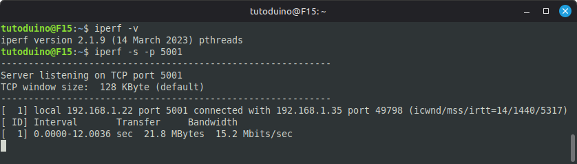
sudo apt install iperfCheck iPerf version and start iPerf server. It is listening on port 5001 on my Linux PC with IP 192.168.1.22.
iperf -v
iperf -s -p 5001The result should be the following:
2/ Install iPerf2 Client on EPS32
We will use the example provided on Espressif IoT Development Framework on GitHub to enable an iPerf client on ESP32. Here is the procedure to compile and upload this example for ESP32-C3:
# ESP-IDF setup
mkdir ~/esp
cd esp/
git clone --recursive https://github.com/espressif/esp-idf.git
cd esp-idf/
./install.sh
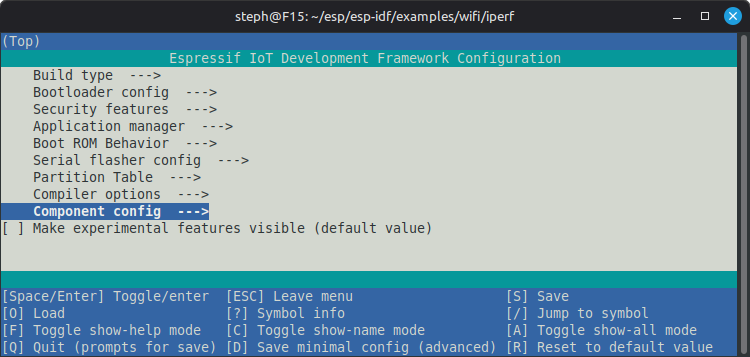
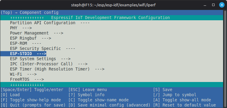
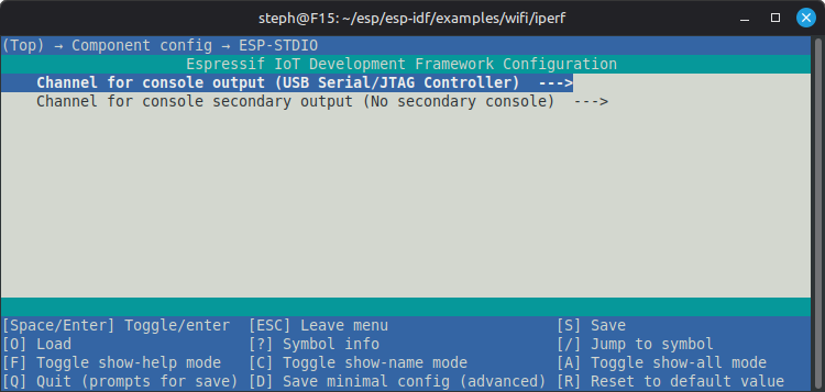
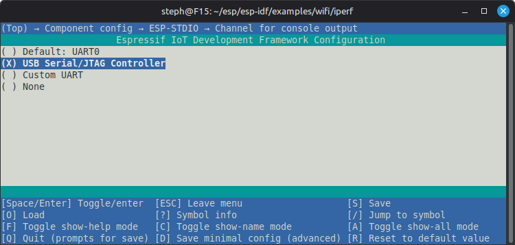
source ./export.shTo use iPerf interactive tool, it is necessary to configure USB Serial / JTAG Controller as console output
# Configure
idf.py menuconfigConfigure ESP-IDF using these steps:
You can then build, flash, and monitor the iPerf example with these commands:
# iPerf example for ESP32-C3
cd examples/wifi/iperf/
idf.py set-target esp32c3
idf.py -p /dev/ttyACM0 build flash monitorOnce the iPerf program is uploaded to ESP32, you have to connect it to your Wi-Fi access point and launch the test with your PC IP (ex: 192.168.1.22) as iPerf server:
iperf> iperf -c 192.168.1.22 -p 5001 -t 10
I (949047) IPERF: mode=tcp-client sip=localhost:5001, dip=192.168.1.22:5001, interval=3, time=10
I (949047) iperf: Successfully connected
Interval       Bandwidth
iperf>  0.0- 3.0 sec  20.43 Mbits/sec
 3.0- 6.0 sec  22.09 Mbits/sec
 6.0- 9.0 sec  22.05 Mbits/sec
 9.0-12.0 sec  21.27 Mbits/sec
 0.0-10.0 sec  21.46 Mbits/sec
I (961047) iperf: TCP Socket client is closed.
I (961047) iperf: iperf exitThis test shows a bandwidth of 22 Mbit/s for ESP32-C3 with ESP-IDF, which is much higher than 7 Mbit/s acheived with Arduino IDE.
Conclusion
The measurements confirm that Arduino can’t match ESP-IDF performance due to fundamental stack differences.
I hope this tutorial was helpful! Please share your feedback by rating with the stars below or leaving a comment.