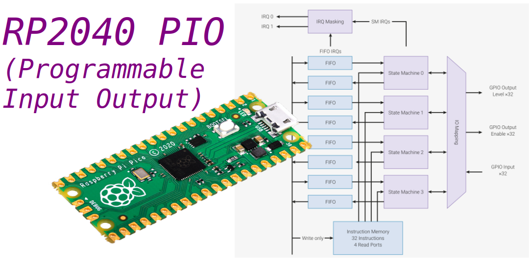
Like other modern microcontrollers, the Raspberry Pi Pico’s RP2040 incorporates several standard interfaces (UART, SPI, I2C, etc.) allowing it to easily communicate with a wide variety of peripherals. But the RP2040 differs from other microcontrollers because it incorporates programmable inputs/outputs (PIO) allowing you to create your own interfaces or to implement specific interfaces that would not be managed natively by the RP2040. A great example of using PIOs is interfacing NeoPixel LED strips as we will see in this article.
How do PIOs work?
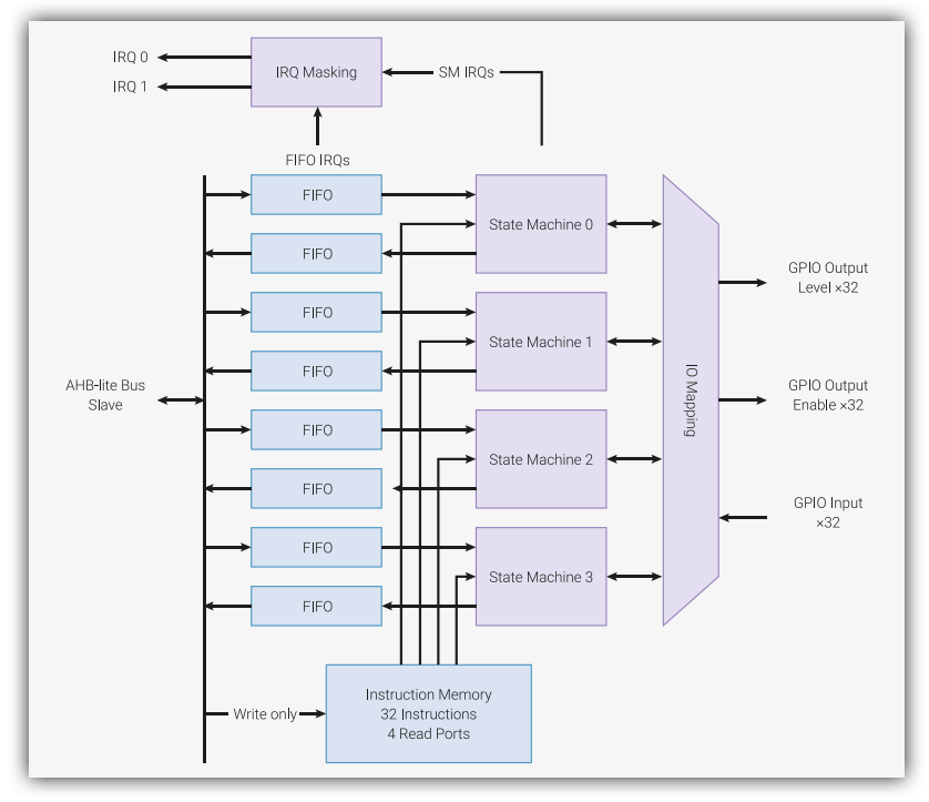
The RP2040 incorporates 2 PIO blocks. Each PIO block is comparable to a small processor which executes the code independently of the CPU (Cortex-M0+). The PIOs thus make it possible to manage the inputs/outputs in a deterministic way, the timing being very precise whatever the CPU load.
Each PIO block is made up of 4 state machines which can independently execute small programs whose instructions are stored in a shared memory (Instruction Memory). At each system clock cycle, each state machine fetches, decodes, and executes an instruction. Each state machine is used to manipulate GPIOs and transfer data. The programs are written with a specific assembler composed of 9 instructions: JMP , WAIT , IN , OUT , PUSH , PULL , MOV , IRQ , and SET.
On the RP2040, all 30 user GPIOs (GP0-GP29) can be used as PIOs.
Example: generating a square wave
For the sake of simplicity, our first program will be written in MicroPython.
We want the PIO to produce a square signal on the GP28 output.
The system clock frequency is 125 MHz by default on the RP2040. State machines run at the default system clock rate.
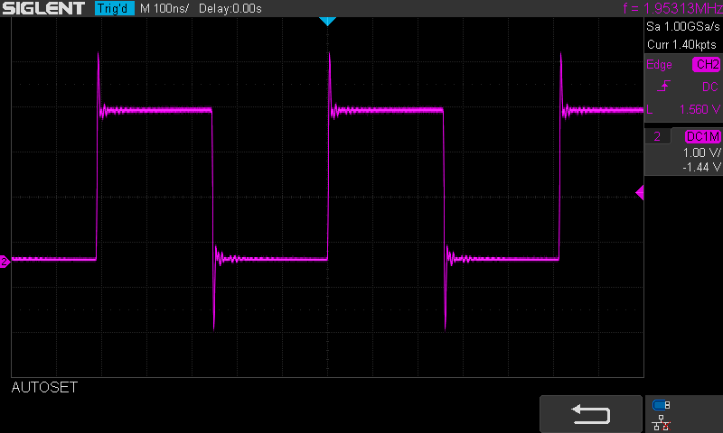
We are going to program a state machine so that it sets the output to its high state for 32 cycles or 256 ns (1 cycle = 1/125000000 Hz = 8 ns) and then it sets the output to its low state for 32 cycles as well. The square wave frequency will therefore be 1/0.000000512 s = 1.953 MHz.
Let’s detail the state machine program (see the documentation of the rp2 library):
wrap_target()Specifies the start location of the program loop.
set(pins, 1) [31]Sets the output to the high state (instruction executed in 1 cycle) and remains in this state for 31 cycles. This step therefore lasts 32 cycles.
set(pins, 0) [31]Sets the output to the low state (instruction executed in 1 cycle) and remains in this state for 31 cycles. This step therefore also lasts 32 cycles.
wrap()Specifies where the program loop ends.
Here is the code written in MicroPython that we will transfer to the Raspberry Pi Pico and which will program the PIO state machine as we have just defined it:
import time
import rp2
from machine import Pin
@rp2.asm_pio(set_init=rp2.PIO.OUT_LOW)
def blink():
    wrap_target()
    set(pins, 1)   [31]
    set(pins, 0)   [31]
    wrap()
sm = rp2.StateMachine(0, blink, set_base=Pin(28))
sm.active(1)
We observe a square signal of frequency 1.953 MHz at the output of pin 34 (GP28) of the Pico.
It is possible to modify the frequency of the square signal by varying the number of cycles during which the state machine leaves the output high and low (parameter 31 for example in this line of code set(pins, 1) [31]). But it is also possible to change the operating frequency of the state machine in the call to the rp2.StateMachine() function.
import time
import rp2
from machine import Pin
@rp2.asm_pio(set_init=rp2.PIO.OUT_LOW)
def blink():
wrap_target()
set(pins, 1)
set(pins, 0)
wrap()
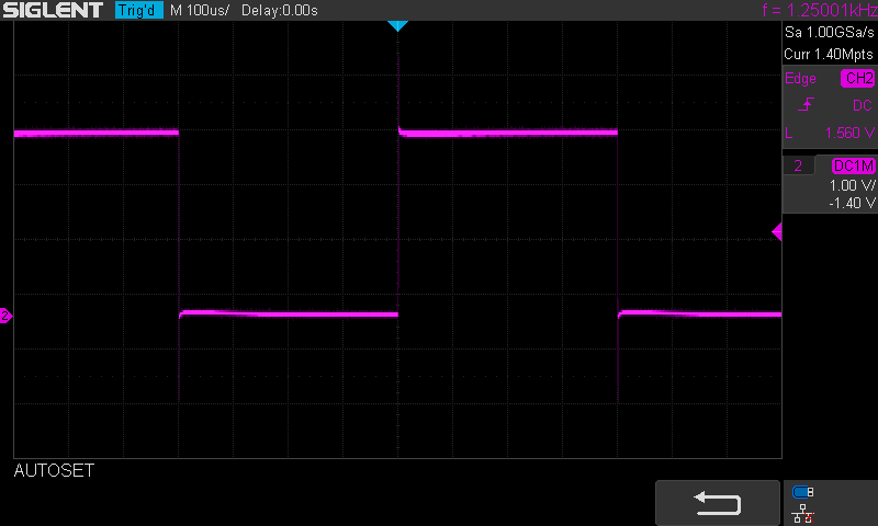
sm = rp2.StateMachine(0, blink, freq=2500,set_base=Pin(28))
sm.active(1)In the example above, the state machine clock is set to a frequency of 2500 Hz. The square wave will therefore have a frequency of 1250 Hz, which is well confirmed by the oscilloscope reading.
Using the PIO to control NeoPixel LED strip
The NeoPixel LED strip control is an excellent example of the use of PIOs.
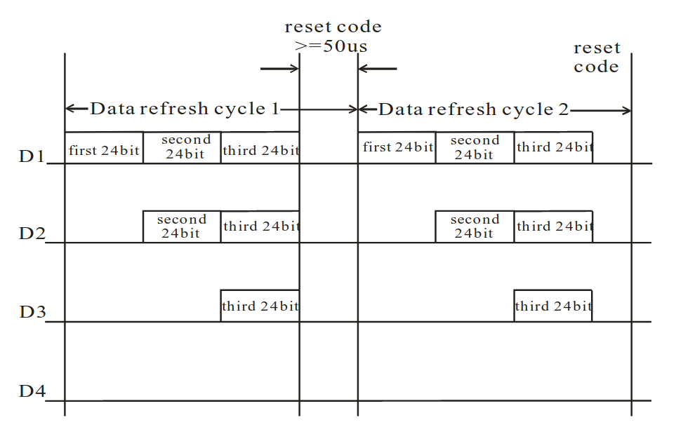
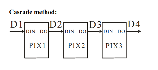
The principle of NeoPixel LEDs (see the data sheet for the WS2812B component integrated into each NeoPixel LED) is to send a table of 24-bit words corresponding to the colors of all the LEDs in the strip. Each LED uses the first 24-bit word it receives on its DIN pin to position its own color and transmits to the following LEDs on its DO pin the sequence of 24-bit words (its own 24-bit word being deleted from this list). A pause of 50ms (reset code) is necessary between each sending of a table of 24-bit words.
The coding of the data to be sent is described in is the diagram of the datasheet of WS2812B:
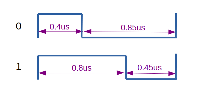
Time constraints must be respected with an accuracy of ±0.15us. The frequency of the state machine clock is set to 5 MHz, so the duration of one cycle is 0.2us. We will therefore approximate the durations of the high and low states at 0.4us and 0.8us because they remain within the tolerance of ±0.15us.
I have simplified the WS2812 example from the RP2040 datasheet, as I find it unnecessarily complicated.
Here my version of the state machine program:
@rp2.asm_pio(set_init=rp2.PIO.OUT_LOW, out_init=rp2.PIO.OUT_LOW, out_shiftdir=rp2.PIO.SHIFT_LEFT, autopull=True, pull_thresh=24)
def ws2812():
# 1 step is 0.2us (clock frequency must be set to 5MHz)
wrap_target()
# 1 step at 0 (to wait for data in low state, reset code)
out(x, 1)
# start of the cycle
# 2 step at 1
set(pins, 1) [1]
# 2 step at x
mov(pins, x) [1]
# 1 step at 0
set(pins, 0)
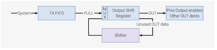
wrap()The state machine is started in “auto-pull” mode, which means that it is not necessary to execute the pull command to retrieve data from the TX FIFO to the OSR.
Details of the program:
out(x, 1)The out(x,1) command copies 1 bit from the OSR to the x register. During this cycle (0.2us), the output is low because we configured set_init=rp2.PIO.OUT_LOW and out_init=rp2.PIO.OUT_LOW. Setting the output to the low state at the start of our program is important because it allows the output to be in the low state while waiting for the first bit of data (reset code).
set(pins, 1) [1]The command set(pins, 1) [1] sets the output to the high state for 2 cycles (the instruction takes executes in 1 cycle and we have added a delay of 1 cycle with the command [1]. A At this stage we do not know if the data bit is 0 or 1. But whether it is 0 or 1, the output must be set high for 2 cycles.
mov(pins, x) [1]The command mov(pins, x) [1] sets the output to the state corresponding to the value of x for 2 cycles.
set(pins, 0)The set(pins, 0) command sets the output low for 1 cycle.
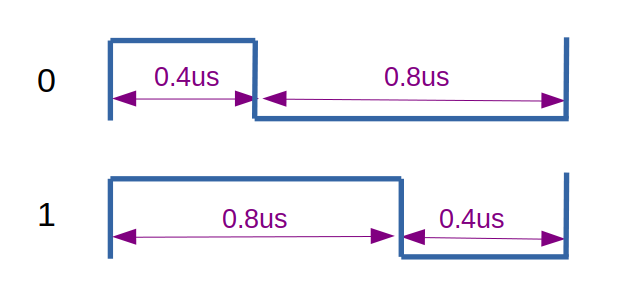
Here is an explanation in image of the coding of a 0 and a 1 with the state machine program:
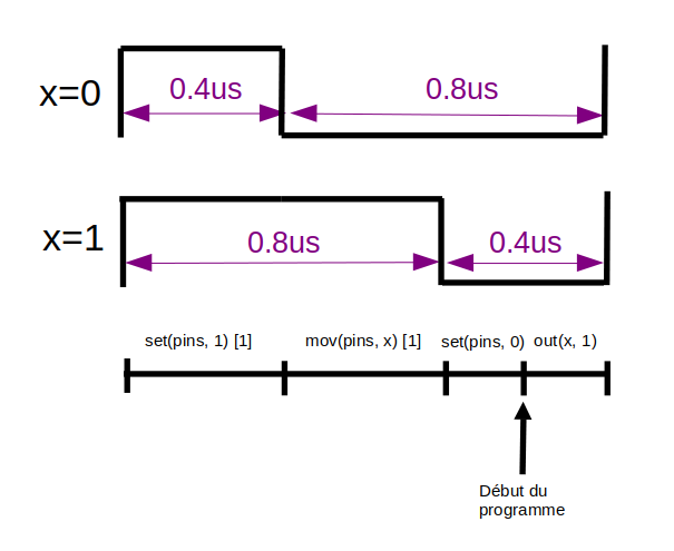
“Début du programme” means “Start of the program in French”, no time to translate the picture, sorry for that 🙂
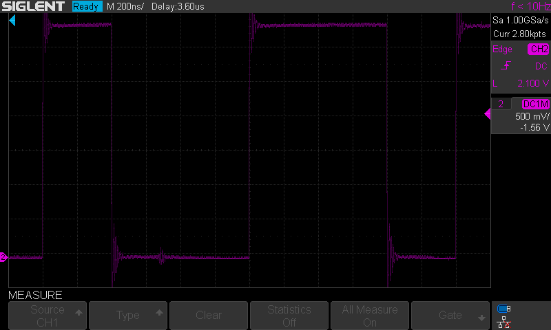
Capture of signals with oscilloscope showing a sequence of bits at 0 followed by a bit at 1:
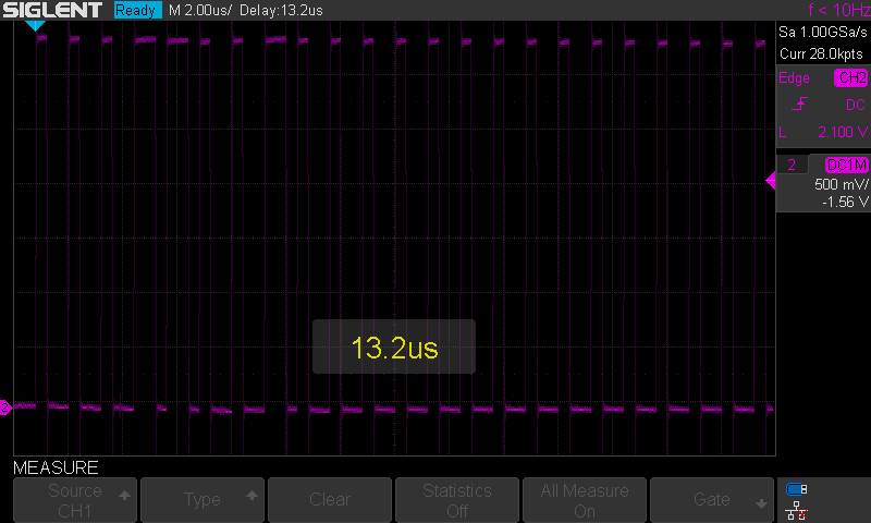
Capture of the control sequence of an LED positioning it in green color with the brightness at 10%. The data sent is 25 for the green component (luminosity of 10% -> 255*10/100 = 25). We observe the binary sequence b00011001 corresponding to 25 on the first data byte which encodes the green component. The next two bytes are at 0 (b00000000), they correspond to the red and blue components.
Here is the complete program in MicroPython which flashes a strip of 10 NeoPixel LEDs:
import array, time
import rp2
import machine

NUM_LEDS = 10
BLACK = (0, 0, 0)
RED = (255, 0, 0)
YELLOW = (255, 150, 0)
GREEN = (0, 255, 0)
CYAN = (0, 255, 255)
BLUE = (0, 0, 255)
PURPLE = (180, 0, 255)
WHITE = (255, 255, 255)
COLORS = (BLACK, RED, YELLOW, GREEN, CYAN, BLUE, PURPLE, WHITE)
BRIGHTNESS = 0.1

def setColor(color):
    r = int(color[0]*BRIGHTNESS)
    g = int(color[1]*BRIGHTNESS)
    b = int(color[2]*BRIGHTNESS)
    return (g<<16) + (r<<8) + b

@rp2.asm_pio(set_init=rp2.PIO.OUT_LOW, out_init=rp2.PIO.OUT_LOW, out_shiftdir=rp2.PIO.SHIFT_LEFT, autopull=True, pull_thresh=24)
def ws2812():
    # 1 step = 0.2us (clock frequency must be set to 5MHz)
    wrap_target()
    # 1 step at 0 (to wait for data in low state, reset code)
    out(x, 1)
    # start of the cycle
    # 2 step at 1
    set(pins, 1) [1]
    # 2 step at x
    mov(pins, x) [1]
    # 1 step at 0
    set(pins, 0)
    wrap()

sm = rp2.StateMachine(0, ws2812, freq=5_000_000, set_base=machine.Pin(12), out_base=machine.Pin(12))
sm.active(1)

ar = array.array("I", [0 for _ in range(NUM_LEDS)])

# Set all leds to green
for i in range(NUM_LEDS):
    ar[i] = setColor(GREEN)
sm.put(ar, 8)
time.sleep_ms(50)

# Rotate one red led
cpt = 1
while True:
    ar[cpt-1] = setColor(GREEN)
    ar[cpt] = setColor(RED)
    sm.put(ar, 8)
    time.sleep_ms(50)
    cpt = (cpt+1)%NUM_LEDS
Thank you for your interest in this article. If you liked it, you can rate it by clicking on the stars below or by leaving a comment. I also point out my article on the XIAO RP2040 module and the PIO control of its RGB LED in Rust language .
Excellent tutorial. Thanks for posting it.
Thank you
[…] be using a PIO program to generate all of these signals (one program per signal) and, as you might guess, each of […]
[…] array signal. I will then use a DMA (direct memory access) to copy each array entry in turn to a PIO. The PIO will in turn copy those data values to the relevant GPIO pins. The PIO will update the pin […]
I have rp2040 and dso of 100mhz i want to generate pwm in 100mhz in PIO. can i get help in code side
If you can accept the first update being wrong, this shorter version will work @2.5MHz
set(pins, 1)
mov(pins, x)
out(x, 1) .side(0)
Ouch, I did not account for the autopull blocking 🙁
I reckon it can be even more compact if you use sideset on the out command to set the pin to 1.
This way you can work at 2.5 MHz and avoid the delays. Not a huge gain but one instruction less.
Thanks for a very well-thought-out post.
Hi there! Thanks for your article!
Would you see a possibility to read Neopixel data via the programmable IO, extract some pixel data to use in a micropython script and pass the remaining data on using the second PIO?
In theory this should work.
Thanks!