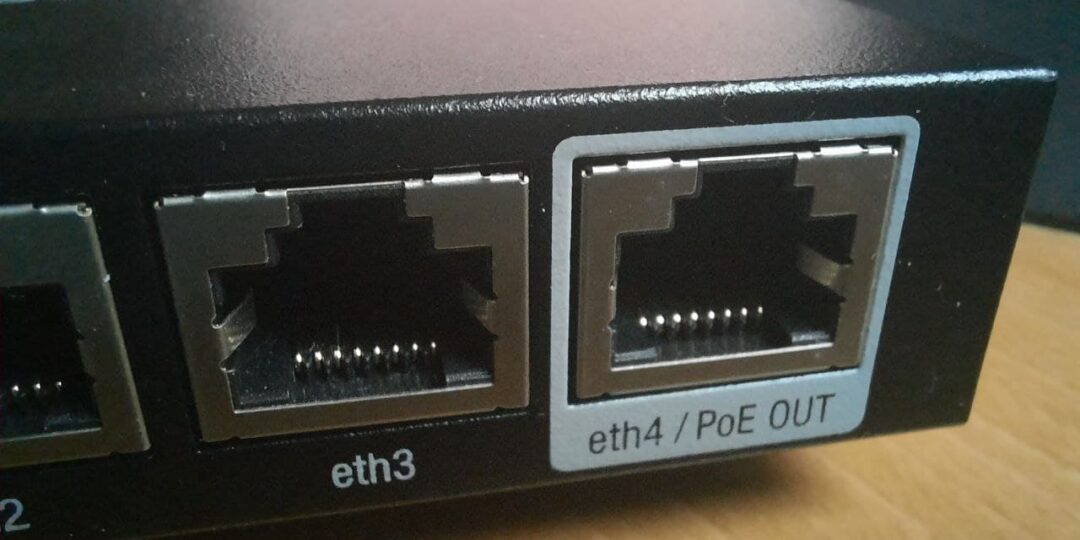
Power over Ethernet (PoE) allows equipment to be powered by the Ethernet cable. This technology is widely used to power surveillance cameras and IP phones. Simply connect the equipment with a simple Ethernet cable, it is no longer necessary to connect it to an external power supply.
The equipment that supplies the power is called Power Sourcing Equipment (PSE). The equipment which is on the other side of the cable and which consumes the current is called Powered Device (PD).
This technology was defined in 2003 by the IEEE 802.3af standard. It originally made it possible to provide a power of 15.4 W (Type 1) using 2 pairs of cable with a current of 350 mA maximum under a voltage of 44 V to 57 V.
In 2009 the IEEE 802.3af standard was replaced by the IEEE 802.3at standard. This standard called PoE+ makes it possible to provide a power of 30 W (Type 2) using 2 pairs of cable with a voltage of 44 V to 57 V. A category 5 cable is essential from this standard.
In 2018, the new 802.3bt standard called PoE++ makes it possible to reach a power of 60W (Type 3) or 90 W (Type 4) using the 4 pairs of the Ethernet cable.
Example of using PoE
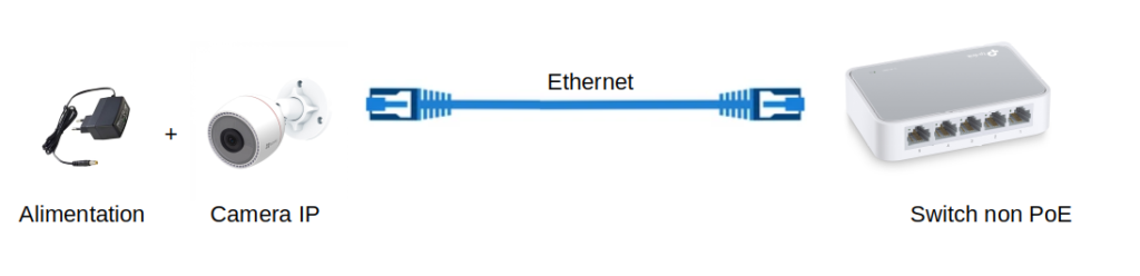
Take the example of an IP camera. The camera requires power to operate and transmit its images to the Switch via the Ethernet cable. The installer will therefore have to position the camera near a power outlet or pull an electrical outlet to the camera in addition to the Ethernet cable.
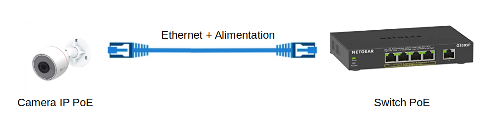
The use of PoE will simplify the installation of the camera. It is no longer necessary to have a power source at the place of its installation. Indeed the PoE Switch will generate the current which will be transmitted by the Ethernet cable to the camera. The Switch and the camera must of course both support the PoE standard.
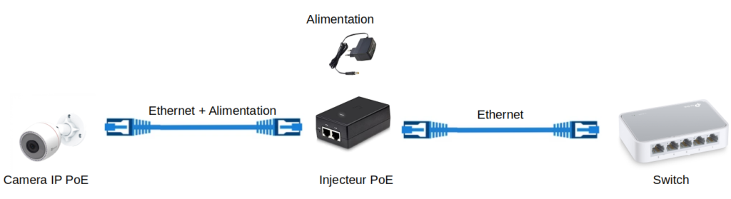
PoE injector
If your Switch is not compatible with the PoE standard, it is possible to use a PoE injector. The injector adds power from the external power supply to the data from a non-PoE Switch and transmits power and data to the PD (e.g. camera).
PoE splitter
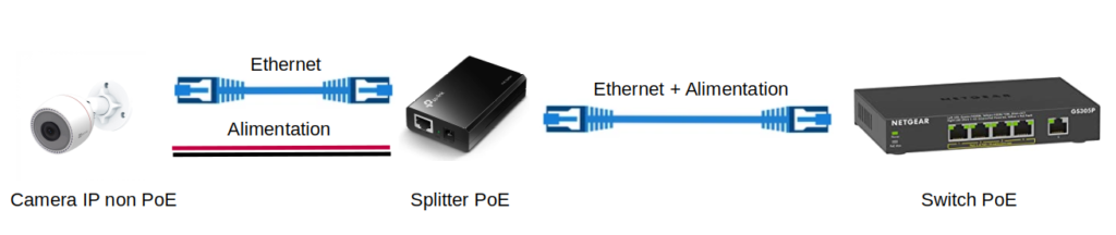
If your equipment (IP camera in the diagram below) is not compatible with the PoE standard, it is possible to use a PoE Splitter. Some Splitters provide a configurable output voltage (e.g. 5 V, 9 V or 12 V) on a DC connector. Other Splitters supply 5 V via a USB output.
Power supply diagrams
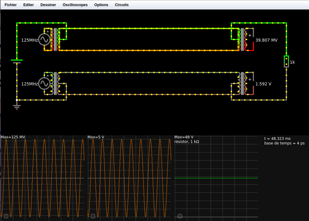
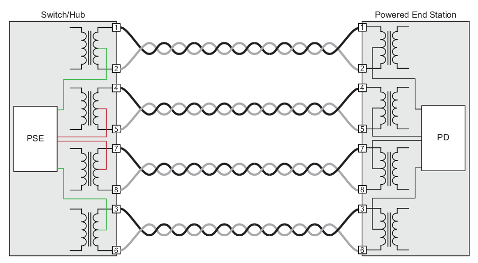
The principle of Power over Ethernet (PoE) is to use center-tapped transformers. In the diagram below, the data signal which is clocked at a symbol rate of 125 MHz is applied to the input of the two transformers on the left (pair 1/2 for the top transformer and pair 3/6 for the transformer on the low for example). A DC voltage of 48 V is applied between the two central taps of the two transformers on the left. The data signal is recovered at the output of the two right-hand transformers. The voltage of 48 V is recovered between the two central taps of the right transformers. The current is thus transmitted on the same pairs as the data without disturbing their operation.
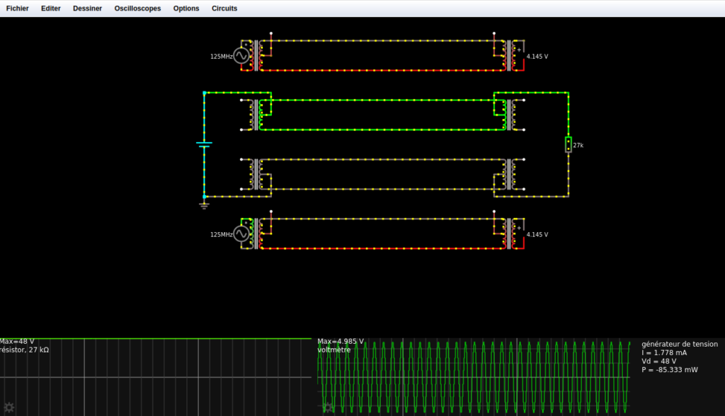
Here is a link to this falstad simulation of a 2-pair power diagram of an Ethernet cable. We can clearly see on the first two oscilloscopes that the data is not altered by the 48 V DC voltage and that the 48 V DC voltage is also not altered by the data signal.
Principle of operation of a center-tapped transformer
A center-tapped transformer adds a voltage to the output signal of the transformer. Here is an example of this principle simulated on the bottom diagram of this falstad simulation.
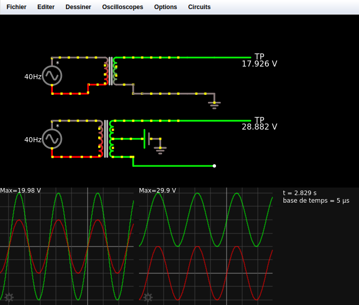
The top circuit shows the use of a center-tapped transformer with a ratio of 2. The input signal is a sine wave voltage of 10 V at 40 Hz. The oscilloscope on the lower left shows the input voltage in green and in red the output voltage of the transformer. We can see that the output signal is at the same frequency as the input signal but its voltage is 20 V. Which is twice the input voltage since the transformer has a ratio of 2.
The bottom circuit uses a center-tapped transformer to which a DC voltage of 20 V is applied. The oscilloscope at the bottom right displays in green the input voltage which varies between -10 V and +10 V at a frequency of 40 Hz as for the upper circuit. The output voltage in red on the oscilloscope always has the same frequency of 40 Hz, but on the other hand the output voltage varies between +10 V and +30 V.
Current injection modes (Mode A, Mode B)
The 802.3 standard defines two alternatives for the injection of current into the cable by the PSE:
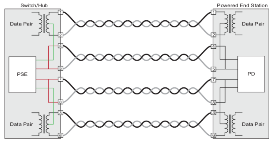
- Mode A: Power is supplied through the center taps of the coupling transformers on pairs 1/2 and 3/6.
- Mode B: Power is supplied via pairs 4/5 and 7/8 in the case of 10BASE-T/100BASE-TX, and via the center taps of the coupling transformers on pairs 4/5 and 7/8 in the case of 1000BASE-T.
As I explain in my Ethernet article, 10BASE-T and 100BASE-TX Ethernet only use 2 pairs (1/2 and 3/6) to carry data. In mode A the current is transmitted on the same pairs as the data (1/2 and 3/6). In mode B, the 2 pairs not used for data (4/5 and 7/8) are used to carry the current.
1000BASE-T Ethernet uses the 4 pairs of the cable to transmit data at 1 Gbit/s. The current is therefore necessarily conveyed on the same pairs as the data. With PoE++, it is possible to pass the current on the 4 pairs at the same time to have more power.
It is possible to simulate the power scheme under Falstad. In the example below we simulate the 100BASE-TX Ethernet power scheme with a PSE in mode B.
PSE End-span vs. PSE Mid-span
A PSE can be End-span or Mid-span.
An End-span PSE supplies PoE power directly to a PD. A PoE Switch is an example of End-span.
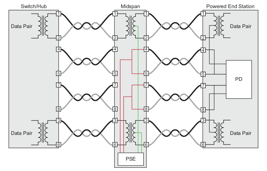
A Mid-span PSE serves as an intermediate device between a non-PoE capable switch and a PoE capable PD. A PoE injector is an example of a mid-span PSE.
Power Schematic for a Mid-span PSE
Polarities used by the PSE
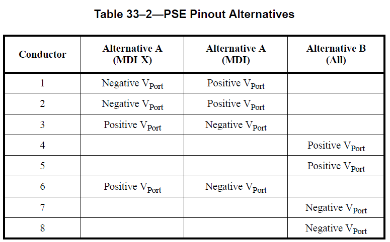
We often find approximations on the polarities of PoE. To be precise, the IEEE standard distinguishes 3 alternatives for PoE polarities on a PSE:
- MDI-X PSE using Mode A
- MDI PSE using Mode A
- PSE using Mode B
Note that PSEs that use auto-configuring (“Auto MDI-X”) MDI/MDI-X ports can choose either polarity choice associated with the Alternate A configurations.
PoE et Arduino
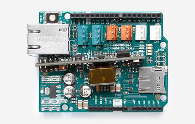
There was an Ethernet Shield including a PoE module for Arduino Uno. Unfortunately this module is no longer available on the Arduino site.
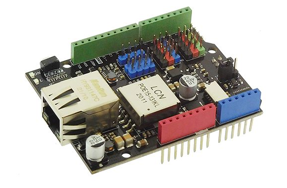
A PoE Ethernet Shield from DFRobot (ref DFR0850) is available, but I did not test it.
PoE and Raspberry Pi
The Raspberry Pi 4 Model B uses an RJ45 connector reference Trxcom TRJG0926HENL, here is the internal diagram:
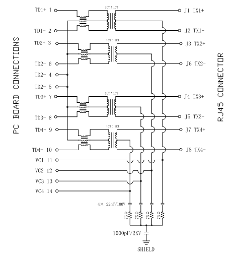
The 4 central sockets of the coupling transformers (VC1..VC4) are connected to the 4-pin “PoE” connector of the Raspberry Pi. It is therefore possible to recover the PoE current directly via these pins.
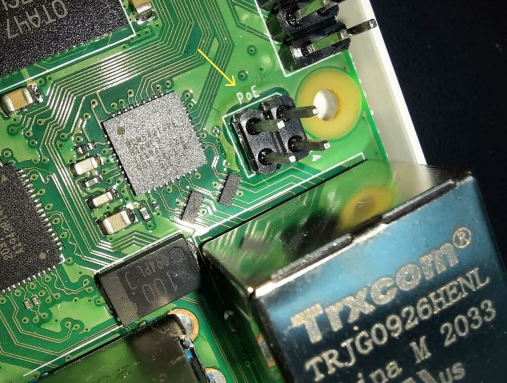
Be careful, the voltage on these terminals is not 5 V but about 48 V. You must not power the Raspberry Pi directly via these pins but use a PoE module. For example, this module allows you to transform the PoE power supply into a 5 V power supply for the Raspberry Pi.
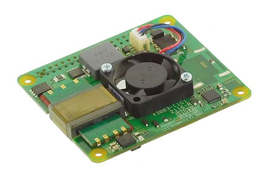
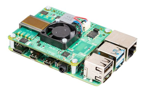
The PoE HAT modules below allow you to power a Raspberry Pi via a simple Ethernet cable.
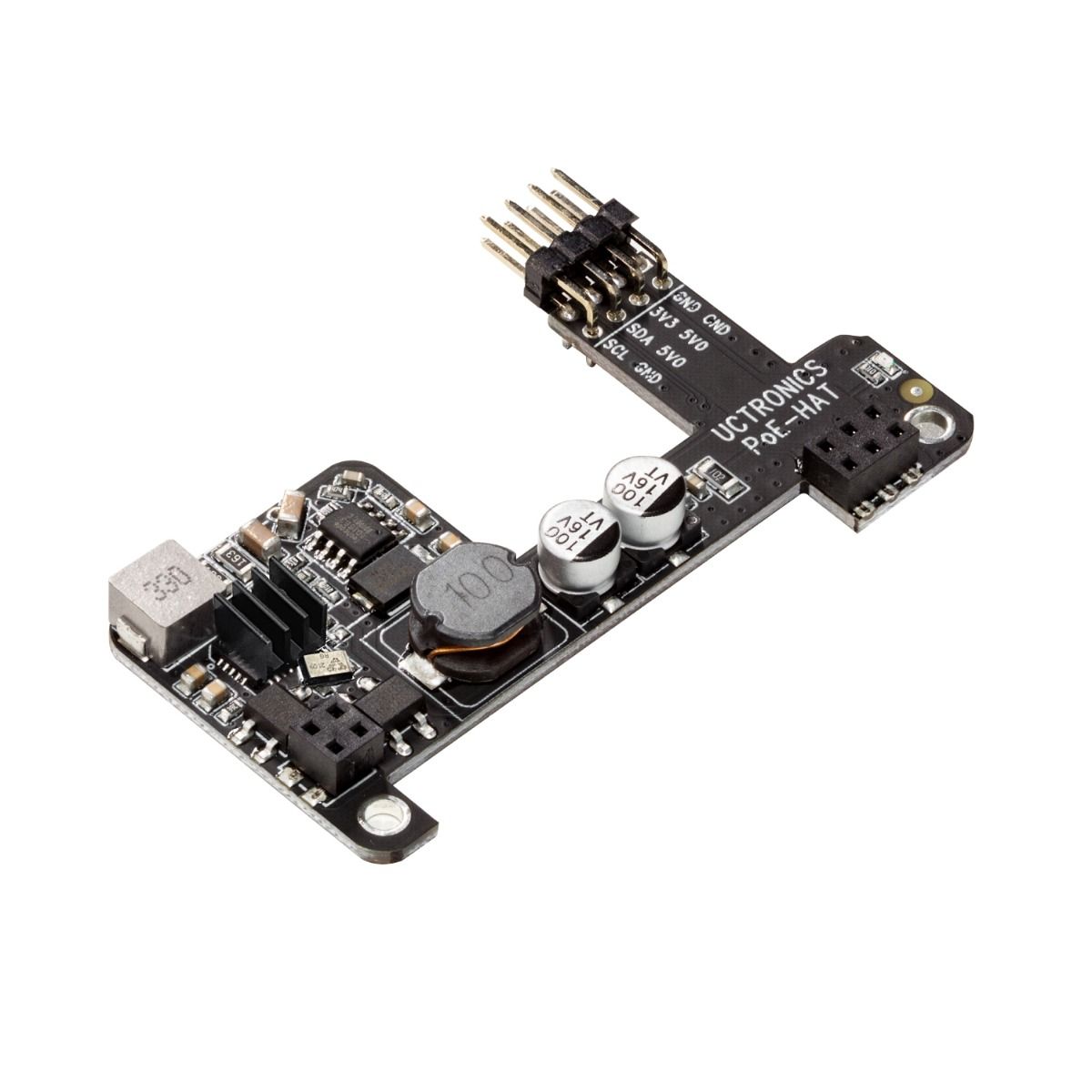
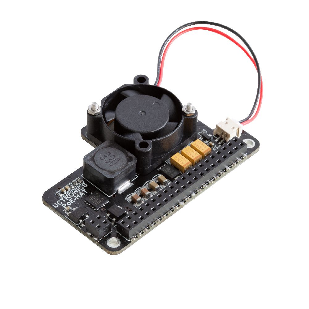
You will find in this article a comparative test of different PoE HAT for Raspberry Pi.
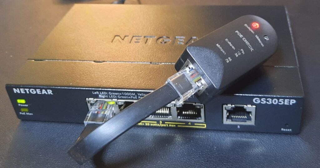
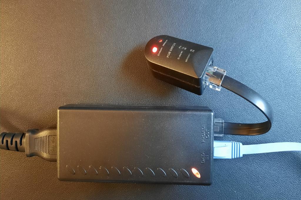
PoE Tester
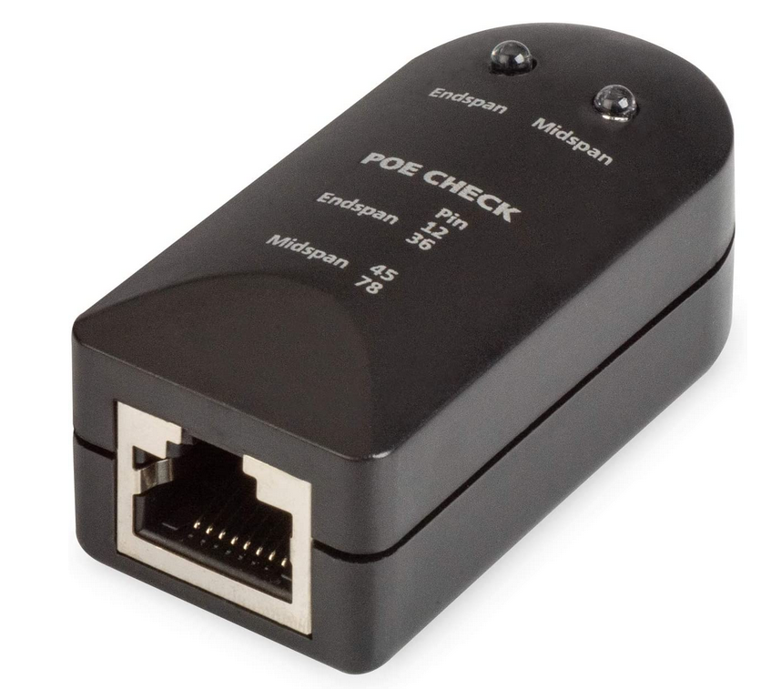
This type of tester makes the shortcut that an End-span necessarily uses Mode A and a Mid-span necessarily uses Mode B. If this is often the case, it would have been more accurate to indicate Mode A / Mode B instead of Endspan / Midspan on the tester. Because it is the Mode that the tester allows to check.
As seen in the following photos, the tester does not allow to test if it is an Endspan or Midspan type PSE, but only if it uses Mode A (LED Endspan) or Mode B ( Midspan LEDs).
Feel free to leave a comment, thank you for reading!