How to make an LED blink?
To begin, we must understand how to wire our assembly. I invite you to read the section of my site on the basics of electronics. As I indicate, an LED emits light when a current passes through it. The intensity of the current flowing in an LED must be between 5 and 20 mA depending on the desired luminosity. The stronger the current, the brighter the LED. But be careful not to exceed 20 mA so as not to destroy the LED.
The role of the resistance is to limit this current, and it is therefore necessary to calculate this resistance in order to have a current of approximately 15 mA. We are going to use a digital output from the Arduino Uno to power our LED. You should know that a digital output of the Arduino has a voltage of 5 V when it is in the HIGH state (HIGH). By applying Ohm’s Law, we determine that the resistor to be used should have the value of approximately 300 Ω ?
Here are the details of the calculation (attention as we will see below it is an approximation because the voltage across the LED is not taken into account):
U = R x I
R = U / I = 5 V / 0.015 A = 333 Ohm
We will therefore use a resistor of 300 Ω to supply the LED with a current of 16 mA. It is possible to put this resistor between the output pin of the Arduino and the anode of the LED, or between the cathode of the LED and the ground.
What happens if we forget to put this resistor and the LED is connected directly between the output of the Arduino Uno and the ground? Well, the LED will be destroyed because the current that will flow through it will be too high.
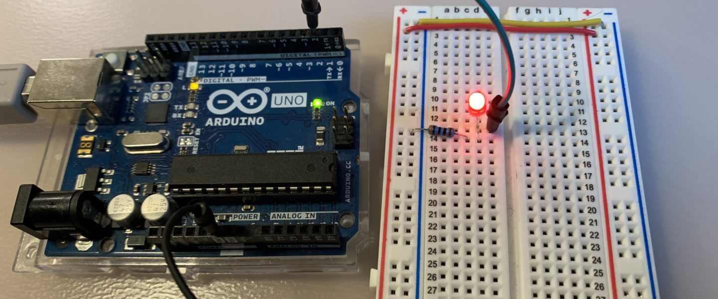
To make the LED blink we will connect it to a digital output of the Arduino Uno. Simply vary the state of this output to turn the LED on or off. The LED is off when the output is LOW and the LED is on when the output is HIGH.
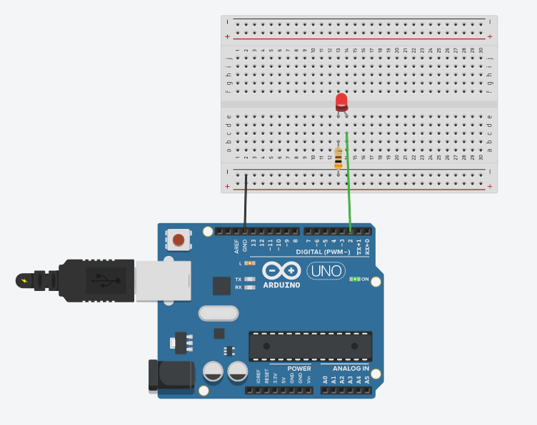
The schematic
Here is the schematic, we are using digital output 2 from the Arduino Uno and a 300 Ω resistor.
The program
Here is the sketch (program) that will run on our Arduino:
// Clignotement d'une LED rouge
// https://tutoduino.fr/
// Copyleft 2020

// La LED est reliee sur la broche 2 de l'Arduino Uno
#define BROCHE_LED_ROUGE 2

void setup() {
  // Declare la broche sur laquelle la LED est
  // reliee comme une sortie de l'Arduino Uno
  pinMode(BROCHE_LED_ROUGE, OUTPUT);
}

void loop() {
  // Passer le sortie de l'Arduino à l'état HAUT pour allumer la LED
  digitalWrite(BROCHE_LED_ROUGE, HIGH);

  // Attendre 1 seconde, pendant ce temps le processeur ne fait rien
  // et la LED reste donc allumee
  delay(1000);

  // Passer le sortie de l'Arduino à l'état BAS pour eteindre la LED
  digitalWrite(BROCHE_LED_ROUGE, LOW);

  // Attendre 1 seconde, pendant ce temps le processeur ne fait rien
  // et la LED reste donc éteinte
  delay(1000);
}
Here is the video :
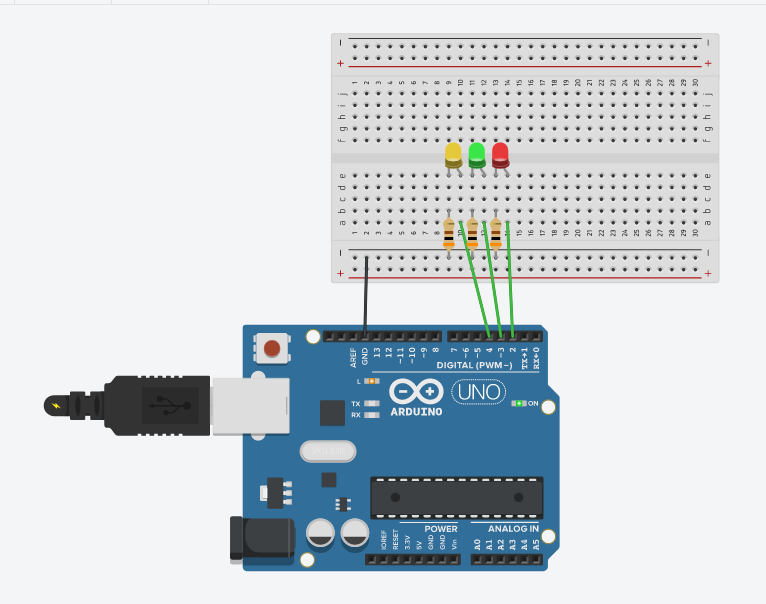
Blink multiple LEDs
We will see that it is also simple to make several LEDs flash. Simply connect each LED to a different output of the Arduino and add a resistor per LED.
// Clignotement de plusieurs LED
// https://tutoduino.fr/
// Copyleft 2020

#define BROCHE_LED_ROUGE 2
#define BROCHE_LED_VERTE 3
#define BROCHE_LED_JAUNE 4

void setup() {
  pinMode(BROCHE_LED_VERTE, OUTPUT);
  pinMode(BROCHE_LED_JAUNE, OUTPUT);
  pinMode(BROCHE_LED_ROUGE, OUTPUT);
}

void loop() {
  digitalWrite(BROCHE_LED_ROUGE, HIGH);
  delay(1000);
  digitalWrite(BROCHE_LED_VERTE, HIGH);
  delay(1000);
  digitalWrite(BROCHE_LED_JAUNE, HIGH);
  delay(1000);
  digitalWrite(BROCHE_LED_VERTE, LOW);
  digitalWrite(BROCHE_LED_JAUNE, LOW);
  digitalWrite(BROCHE_LED_ROUGE, LOW);
  delay(1000);
}
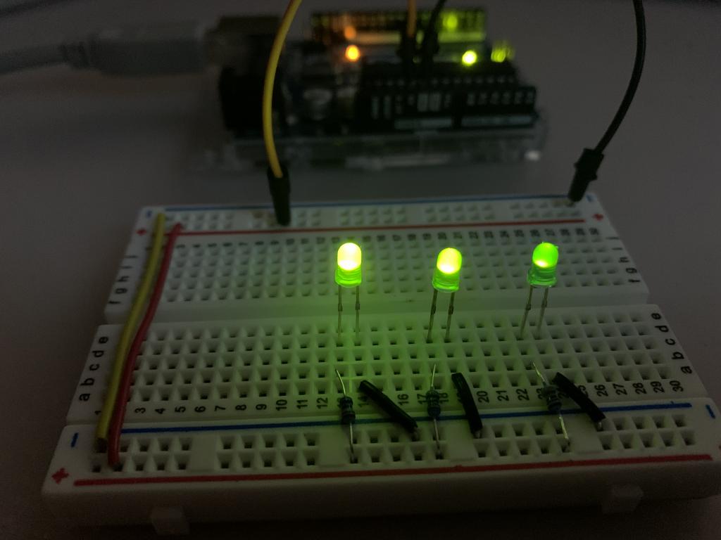
Impact of resistor on LED brightness
As mentioned above, the brightness of the LED depends on the current flowing through it. With a fixed voltage of 5 V, the current is a function of the resistor used.
Here is an example of brightness using 3 different resistors (220 Ω, 470 Ω and 3.3 kΩ) with 3 identical LEDs.
Voltage across an LED
We can consider that the voltage across an LED is equal to its threshold voltage, regardless of the current flowing through it. Different colored LEDs often have different threshold voltages, see this summary table.
Here is the calculation of the current flowing in an LED according to the resistor used and its threshold voltage:
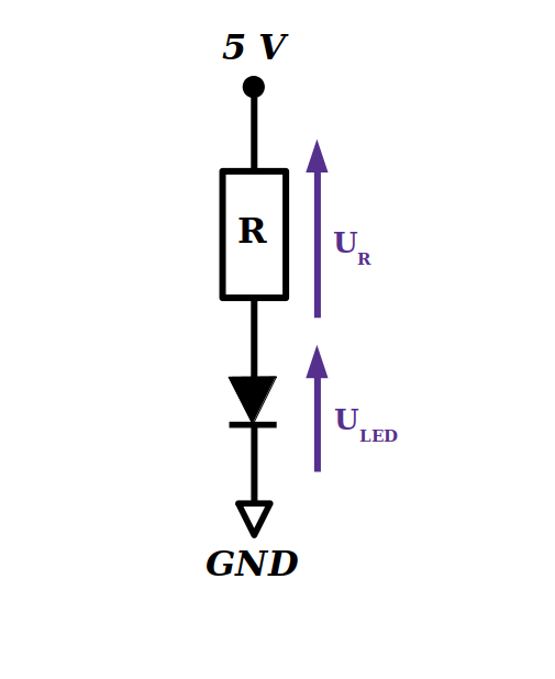
The current flowing through the LED is the same as the current flowing through the resistor.
I = UR / R = (5 – ULED) / R
because
ULED+UR = 5 Volts
For a blue LED, ULED = 2.8 V. With a 220 Ω resistor, we have:
I = (5 – 2.8) /220 = 10mA
For a red LED, ULED = 1.9 V. With a 220 Ω resistor, we have:
I = (5 – 1.9) /220 = 14mA
It will therefore be necessary to take into account the threshold voltage of the LED to correctly calculate the value of the resistor to be used according to the intensity of the desired current.