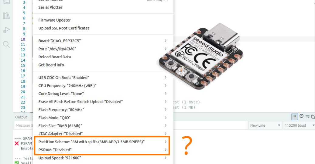
Have you ever noticed the options in the Arduino IDE to enable PSRAM or select a partition scheme for ESP32? Do you know what they actually do? In this tutorial, focused on the ESP32-C5, I’ll walk you through what they mean and how to use them effectively.
I will first introduce all key memory types—FLASH, SRAM, PSRAM, EEPROM—and then partition schemes.
Partitions matter because a well-configured setup unlocks ESP32 capabilities like storing files (e.g., web pages for embedded servers), OTA firmware updates, or settings persistence. Poor configuration risks space shortages, feature loss, or memory corruption, as seen in real-world sketch overflows.
Before exploring ESP32’s advanced memory features, we’ll review basics using the Arduino Uno example to clarify where data lives and how to maximize space across all memory types.
Understanding micro-controller memory using the Arduino Uno as an example
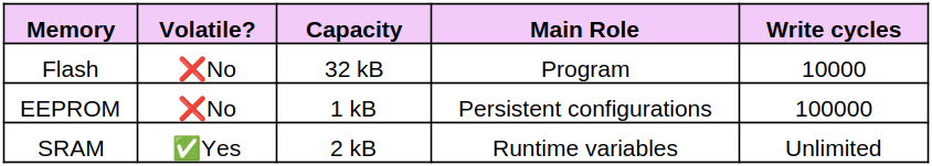
Micro-controllers use different types of memories for different purposes:
- EEPROM: non-volatile memory that retains data even without power. This small-capacity memory type is optimized for frequent writes (100,000 cycles).
- FLASH: like EEPROM memory, FLASH memory is non-volatile and retains data even without power. This memory type generally has greater capacity, but allows fewer write cycles (10,000 cycles).
- SRAM: ultra-fast volatile memory that is erased as soon as power is cut.
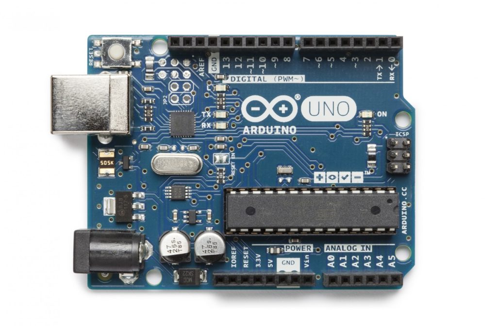
The Arduino UNO R3 is based on the ATMEGA 328P micro-controller, equipped with the following memories according to the documentation for this micro-controller:
- 32 kB FLASH
- 1 kB EEPROM
- 2 kB SRAM
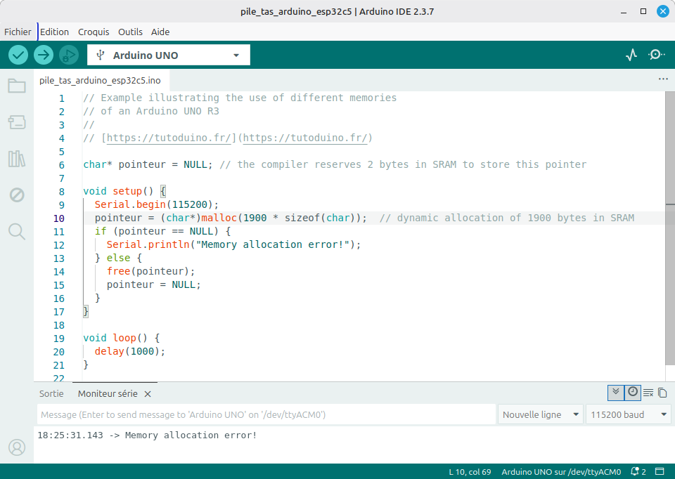
Let’s take the following example program, and explain its memory usage:
// Example illustrating the use of different memories
// of an Arduino UNO R3
//
// [https://tutoduino.fr/](https://tutoduino.fr/)
char* pointeur = NULL; // the compiler reserves 2 bytes in SRAM to store this pointer
void setup() {
  Serial.begin(115200);
  pointeur = (char*)malloc(200 * sizeof(char));  // dynamic allocation of 200 bytes in SRAM
  if (pointeur == NULL) {
    Serial.println("Memory allocation error!");
  } else {
    free(pointeur);
    pointeur = NULL;
  }
}
void loop() {
  delay(1000);
}
Once compiled, the program occupies 2,264 bytes of Flash, leaving 29,992 bytes available out of the total 32 kB of Flash memory. The global variables use 228 bytes of SRAM, leaving 1820 bytes available out of the total 2 kB of SRAM memory.
Sketch uses 2264 bytes (7%) of program storage space. Maximum is 32256 bytes.
Global variables use 228 bytes (11%) of dynamic memory, leaving 1820 bytes for local variables. Maximum is 2048 bytes.Note: Out of the 32,768 bytes (32 kB) of Flash, 512 bytes are reserved for the Arduino bootloader, leaving a maximum of 32,256 bytes for the user program.
If the program tries to allocate more memory than available in SRAM, the allocation will fail. Example here with an attempt to allocate 1900 bytes:
There is no configurable partition scheme in the Arduino IDE for the Arduino UNO R3. Indeed, its micro-controller uses a fixed 32 kB flash memory, without a file system or native OTA support.
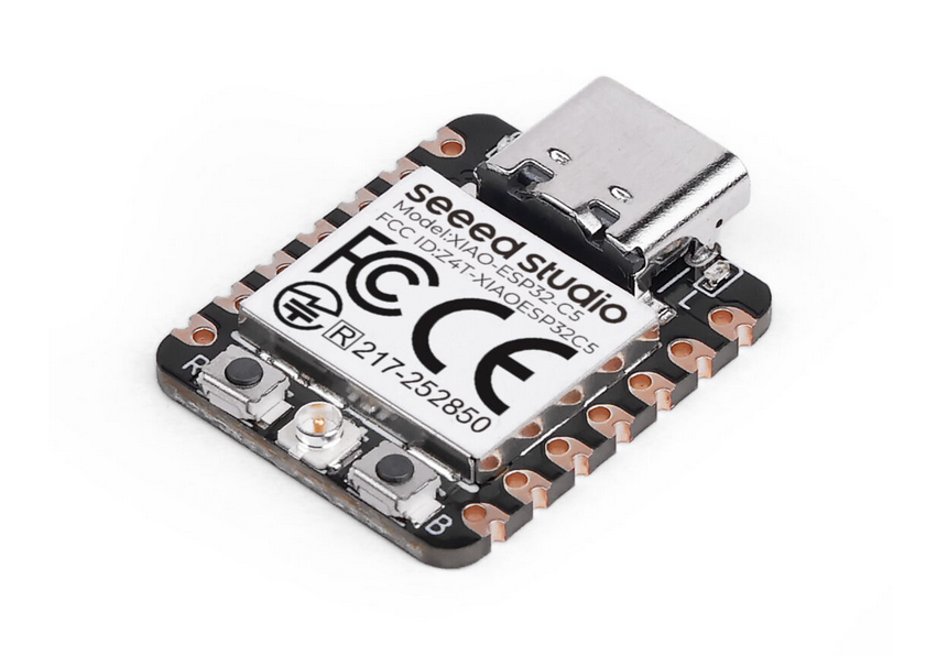
The memory of the XIAO ESP32-C5
The XIAO ESP32-C5 module is based on the ESP32-C5 micro-controller equipped with 8 MB external SRAM as well as 8 MB external FLASH.
The ESP32-C5 micro-controller has the following internal memory:
- 384 kB of high-performance (HP) SRAM, used by the high-performance (HP core) core, which operates at a high frequency (240 MHz).
- 16 kB of low-power (LP) SRAM, associated with the low-power (LP core) core, which operates at a much lower frequency (40 MHz).
- 320 kB of ROM, immutable read-only memory, dedicated to basic functions and system startup.
The virtual address is mapped to the physical address space of the external memory through the MMU. You find in the following table the virtual address of the different memories of the ESP32-C5.
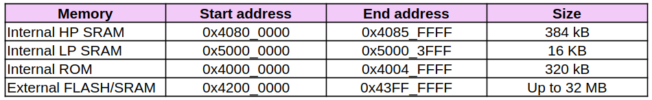
Note: On the XIAO ESP32-C5, external PSRAM and Flash share the 0x42000000–0x43FFFFFF virtual address range because the ESP32-C5 SoC uses a cache/MMU subsystem to map external memories into a common virtual address space. Flash and PSRAM are mapped into this range dynamically via MMU page mappings rather than occupying distinct virtual address regions.
Internal SRAM and external PSRAM of XIAO ESP32-C5
Going back to the beginning of this tutorial, you should remember that dynamic memory allocation is done in SRAM. And it turns out that the ESP32-C5 microcontroller’s internal SRAM is limited to 384 KB.
In case the program requires larger dynamic memory allocation, the 8 MB PSRAM of the XIAO ESP32-C5 module comes in. PSRAM is external memory, connected via SPI, designed to emulate SRAM but using DRAM (Dynamic RAM) technology.
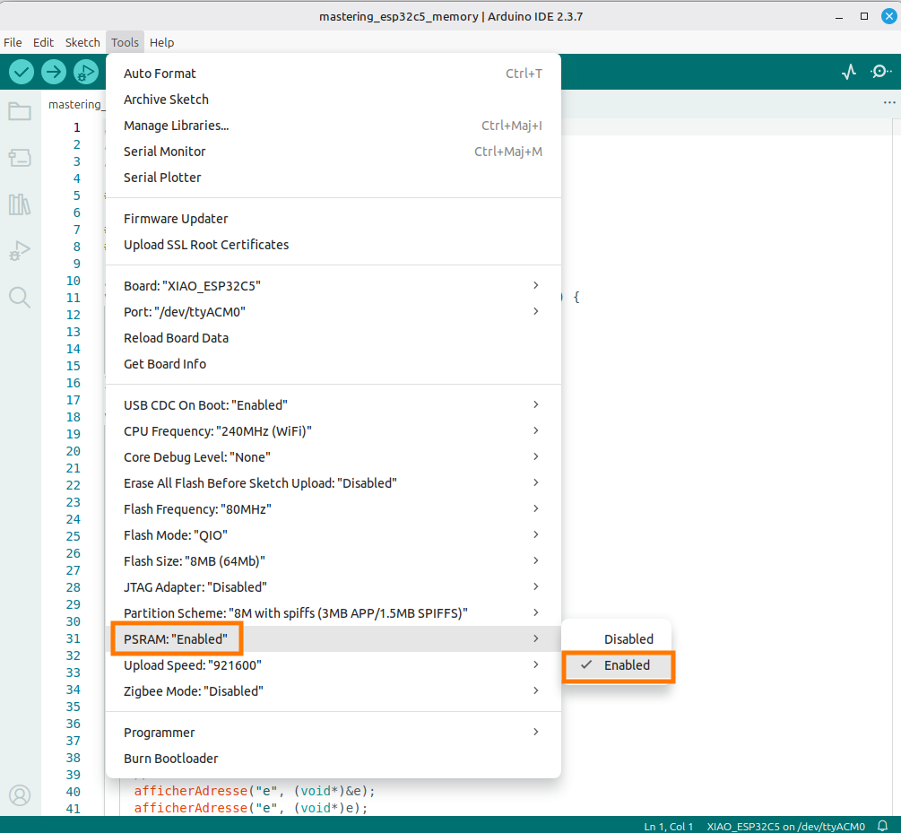
However, the PSRAM is not enabled by default in the ESP32 configuration of the Arduino IDE, you must explicitly enable PSRAM in the IDE settings.
This example demonstrates how the ESP32-C5 automatically selects SRAM for small allocations (1 byte) and PSRAM for large ones (1 MB), with large allocations failing when PSRAM is disabled.
// Example illustrating the use of SRAM and PSRAM
// on a XIAO ESP32C5
// https://tutoduino.fr/en/partition-esp32-arduino-en/
#include <Arduino.h>
/**
 * Function to display the memory address of any variable
 * @param variableName Name of the variable for display
 * @param variable Pointer to the variable to check
 */
void printAddress(const char* variableName, void* variable) {
  Serial.print("Memory address of '");
  Serial.print(variableName);
  Serial.print("' is: 0x");
  Serial.println((uintptr_t)variable, HEX);
}
void setup() {
  int* one_byte_pointer;   // Pointer for small allocation test (1 byte)
  int* one_mbyte_pointer;  // Pointer for large allocation test (1 MB)
  Serial.begin(115200);
  while (!Serial) {};  // Wait for Serial Monitor to connect
  Serial.println("\n=== SRAM vs PSRAM usage on ESP32C5 ===");
  // CHECK PSRAM AVAILABILITY AND STATUS
  size_t psram_total = ESP.getPsramSize();
  size_t psram_free = ESP.getFreePsram();
  if (psram_total == 0) {
    Serial.println("❌ PSRAM not enabled or not detected");
    Serial.println("   Enable PSRAM in Arduino IDE Tools → PSRAM: 'Enabled'");
  } else {
    Serial.println("✅ PSRAM enabled and detected");
    Serial.printf("   PSRAM Total: %d bytes (%.1f MB)\n", psram_total, psram_total / 1024.0 / 1024.0);
    Serial.printf("   PSRAM Free:  %d bytes (%.1f MB)\n", psram_free, psram_free / 1024.0 / 1024.0);
  }
  Serial.println("\n--- Testing small allocation (1 byte) ---");
  // TRY TO ALLOCATE 1 BYTE - Should use internal SRAM (384KB on ESP32-C5)
  one_byte_pointer = (int*)malloc(0x1);  // Allocate 1 byte
  if (one_byte_pointer != NULL) {
    Serial.println("✅ Small allocation (1 byte) succeeded - Uses SRAM");
    printAddress("one_byte_pointer", (void*)one_byte_pointer);
    psram_free = ESP.getFreePsram();
    Serial.printf("\PSRAM Free: %d bytes (%.1f MB)\n", psram_free, psram_free / 1024.0 / 1024.0);
    // Free the allocation
    free(one_byte_pointer);
    one_byte_pointer = NULL;
  } else {
    Serial.println("❌ Memory allocation failed for one_byte_pointer");
  }
  Serial.println("\n--- Testing large allocation (1 MB) ---");
  // TRY TO ALLOCATE 1MB - Should use PSRAM (8MB on XIAO ESP32C5)
  one_mbyte_pointer = (int*)malloc(0x100000);  // Allocate 1 megabyte (1048576 bytes)
  if (one_mbyte_pointer != NULL) {
    Serial.println("✅ Large allocation (1 MB) succeeded - Uses PSRAM");
    printAddress("one_mbyte_pointer", (void*)one_mbyte_pointer);
    psram_free = ESP.getFreePsram();
    Serial.printf("\PSRAM Free: %d bytes (%.1f MB)\n", psram_free, psram_free / 1024.0 / 1024.0);
    // Free the large allocation
    free(one_mbyte_pointer);
    one_mbyte_pointer = NULL;
  } else {
    Serial.println("❌ Memory allocation failed for one_mbyte_pointer");
    Serial.println("   This happens if PSRAM is not enabled or allocation exceeds available space");
  }
}
void loop() {
  // Empty loop - all tests run once in setup()
  delay(1000);
}When PSRAM is disabled, allocating 1 byte succeeds in internal SRAM, but allocating 1 MB fails:
=== SRAM vs PSRAM usage on ESP32C5 ===
❌ PSRAM not enabled or not detected
   Enable PSRAM in Arduino IDE Tools → PSRAM: 'Enabled'
--- Testing small allocation (1 byte) ---
✅ Small allocation (1 byte) succeeded - Uses SRAM
Memory address of 'one_byte_pointer' is: 0x4085C834 (internal SRAM memory)
PSRAM Free: 0 bytes (0.0 MB)
--- Testing large allocation (1 MB) ---
❌ Memory allocation failed for one_mbyte_pointer
This happens if PSRAM is not enabled or allocation exceeds available spaceWhen PSRAM is enabled, 1-byte allocations succeed in internal SRAM while 1MB allocations succeed in PSRAM:
=== SRAM vs PSRAM usage on ESP32C5 ===
✅ PSRAM enabled and detected
   PSRAM Total: 8388608 bytes (8.0 MB)
   PSRAM Free:  8386296 bytes (8.0 MB)
--- Testing small allocation (1 byte) ---
✅ Small allocation (1 byte) succeeded - Uses SRAM
Memory address of 'one_byte_pointer' is: 0x4085C868 (internal SRAM memory)
PSRAM Free: 8386296 bytes (8.0 MB)
--- Testing large allocation (1 MB) ---
✅ Large allocation (1 MB) succeeded - Uses PSRAM
Memory address of 'one_mbyte_pointer' is: 0x42050908 (external PSRAM memory)
PSRAM Free: 7337704 bytes (7.0 MB)The 1 MB allocation uses external PSRAM, which is confirmed by its address range (0x42000000-0x43FFFFFF).
The Arduino IDE Partition Scheme of ESP32 Flash memory
The Arduino IDE Partition Scheme menu allows you to define how the external FLASH memory of ESP32 micro-controllers should be used.
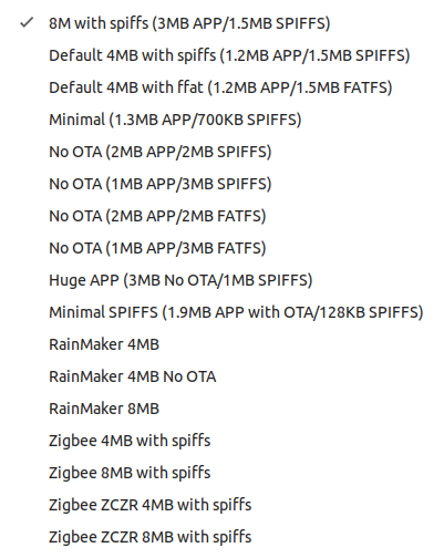
To properly choose a partition scheme on an ESP32, it is essential to understand the acronyms and the roles of each flash memory section:
- SPIFFS (Serial Peripheral Interface Flash File System) is a file system that allows creating, reading, modifying, and deleting files directly in flash memory. This file system manages wear, fragmentation, and data persistence, specific to flash technology. This system does not allow organizing files into folders (all files are at the root).
- FATFS is a file system and a lightweight implementation of the FAT (File Allocation Table) file system designed for embedded systems. It allows organizing files into folders and subfolders and can handle much larger files and partitions than SPIFFS.
- APP (Application) is the partition dedicated to storing the ESP32 firmware (compiled program). The APP partition can be divided into several partitions (e.g., app0, app1) to enable over-the-air (OTA) firmware updates. The app0 partition contains the main firmware (current or previous version), while the app1 partition contains a second copy of the firmware. While a new version is being downloaded to app1, app0 continues to function. After the update, the ESP32 boots from app1.
- OTA (Over-The-Air) is the partition that stores metadata for OTA updates, such as the status of the last update or the active partition (app0 or app1).
Partition schemes are stored in the ESP32 core installation directory for Arduino. For example on Linux:
~/.arduino15/packages/esp32/hardware/esp32/3.3.6/tools/partitionsHere is an example of the partition schemes available for ESP32 core version 3.3.6.
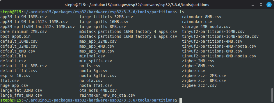
These files in CSV format contain the definition of the partitions:
- Name: Partition identifier (e.g., app0, spiffs).
- Type: Partition type (app, data).
- SubType: Subtype (ota_0, ota_1, spiffs, fatfs, etc.).
- Offset: Offset in hexadecimal in flash memory.
- Size: Partition size in hexadecimal.
- Flags: Additional options (e.g., encrypted).
Here is for example the content of the file default_8MB.csv
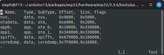
The Arduino IDE uses the selected partition file (.csv) to generate a binary partition table, integrated into the firmware. This table is written to the ESP32‘s flash memory at address 0x8000 during upload. The ESP32 bootloader reads this table during its execution to know where the partitions (APP, SPIFFS, OTA, etc.) are located.
I recommend reading the dedicated partition tables documentation on the Espressif website: https://docs.espressif.com/projects/esp-idf/en/latest/esp32/api-guides/partition-tables.html
Example of a partition scheme-related problem
You want to develop a connected lamp project based on an ESP32-C5, leveraging this micro-controller’s capabilities to create a device compatible with Home Assistant, using the Matter protocol over Thread. This choice allows you to design a secure, interoperable connected object that is easily integrated into an existing home automation ecosystem. I invite you to read my tutorial Create a Matter over Thread temperature sensor based on Seeed Studio XIAO MG24.
For this project, you start from the MatterOnOffLight example provided by Espressif. This example is specifically designed for “connected lamp” applications and integrates Matter protocol support over Thread, greatly simplifying integration with Home Assistant.
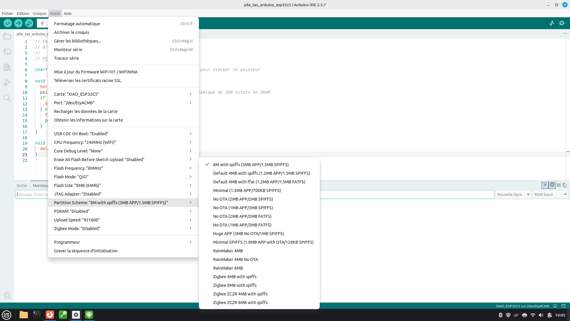
Let’s try using the Minimal partition scheme for this program:
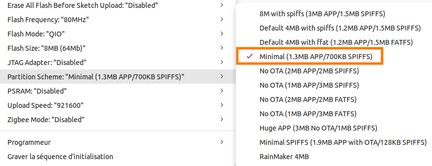
This minimal partition scheme minimal.csv reserves an app0 partition of type app and size 0x140000 (1,310,720 bytes):
# Name,   Type, SubType, Offset,   Size, Flags
nvs,      data, nvs,     0x9000,   0x5000,
otadata,  data, ota,     0xe000,   0x2000,
app0,     app,  ota_0,   0x10000,  0x140000,
spiffs,   data, spiffs,  0x150000, 0xA0000,
coredump, data, coredump,0x1F0000, 0x10000,An error occurs during program compilation. Indeed, the compiled program occupies 2,193,968 bytes, which is greater than the size of the app partition configured by the selected Minimal partition scheme (1,310,720 bytes):
The sketch uses 2,193,968 bytes (167%) of program storage space. The maximum is 1,310,720 bytes.The README file of this example clearly indicates that you must select the Huge APP (3MB No OTA/1MB SPIFFS) partition scheme.
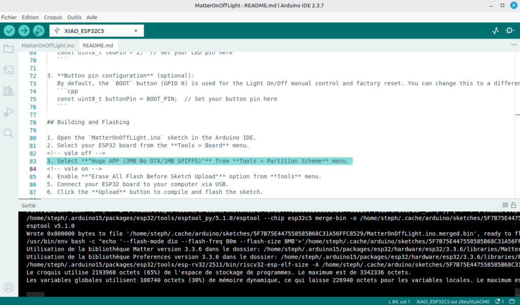
The app0 partition of type app is indeed configured with a size of 0x300000 (3,145,728 bytes) in the huge_app.csv partition scheme:
# Name,   Type, SubType, Offset,  Size, Flags
nvs,      data, nvs,     0x9000,  0x5000,
otadata,  data, ota,     0xe000,  0x2000,
app0,     app,  ota_0,   0x10000, 0x300000,
spiffs,   data, spiffs,  0x310000,0xE0000,
coredump, data, coredump,0x3F0000,0x10000,Once compiled, the firmware occupies 2,193,976 bytes of flash memory. This is well below the maximum of 3,145,728 bytes (3 MB) reserved for our APP partition.
The sketch uses 2,193,976 bytes (69%) of program storage space. The maximum is 3,145,728 bytes.
Global variables use 100,740 bytes (30%) of dynamic memory, leaving 226,940 bytes for local variables. The maximum is 327,680 bytes.I hope this article will inspire you to go further with ESP32-C5. Do not hesitate to give a rating to this tutorial (stars below) and add a comment so that I can know your opinion and improve it if necessary.