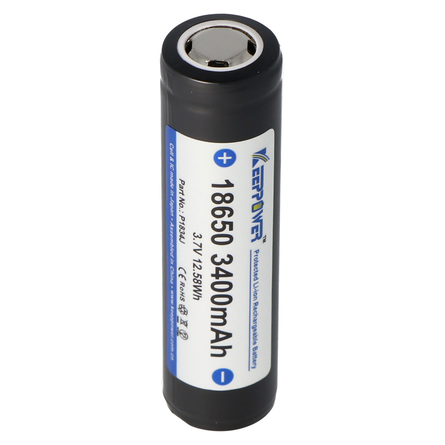
I use several Zigbee temperature sensors in my Home Assistant home automation system. While they work very well, I find their battery life too short. Having to change the CR2032 lithium battery every 4 to 6 months isn’t convenient for me. So I decided to build a Zigbee temperature sensor designed for long battery life and powered by a rechargeable 18650 Li-ion battery.
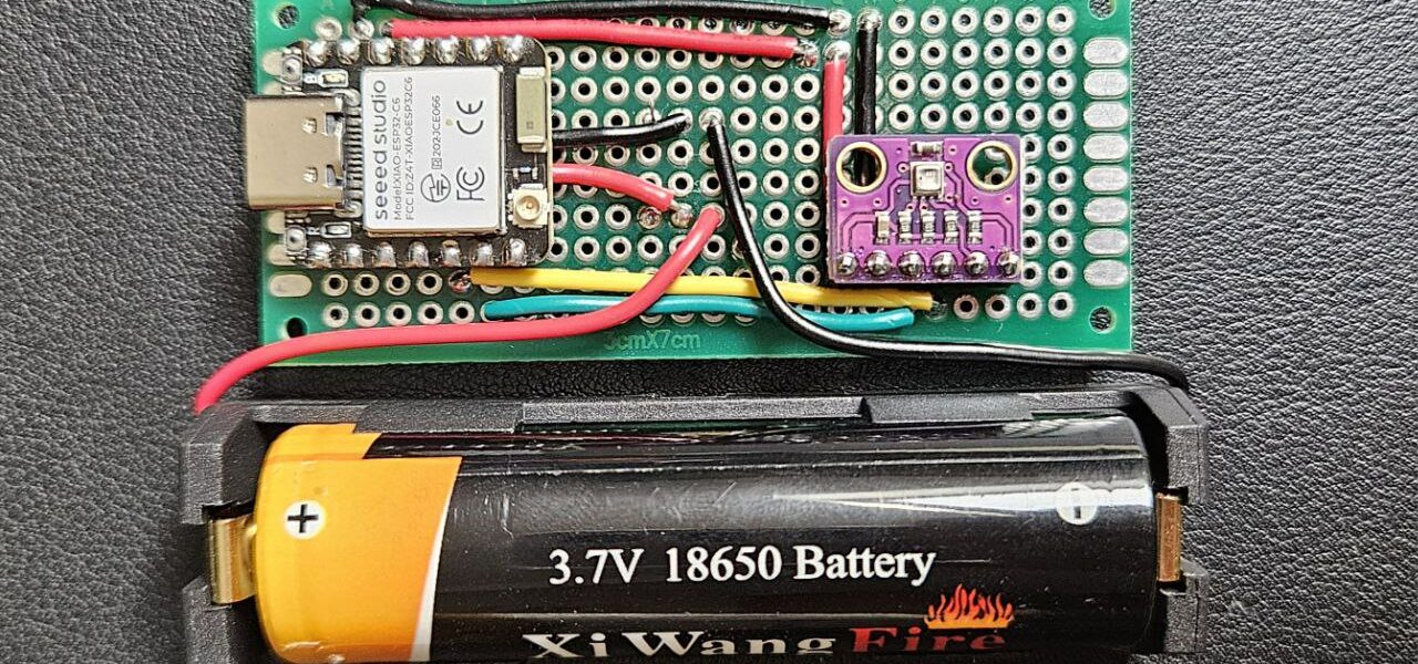
For this tutorial, I’m using the Seeed Studio XIAO ESP32C6 module. This choice was driven by the module’s very low power consumption in deep sleep mode (15 μA) and its battery charging management when powered by its USB-C port.
I’m using a 3.3V BME280 sensor. It measures temperature, humidity, and pressure and communicates with the ESP32C6 via the I²C protocol.
The key to the sensor’s battery life lies in the microcontroller’s deep sleep mode. So, I’ll start by detailing the ESP32C6’s sleep modes and its impact on the Zigbee radio link.
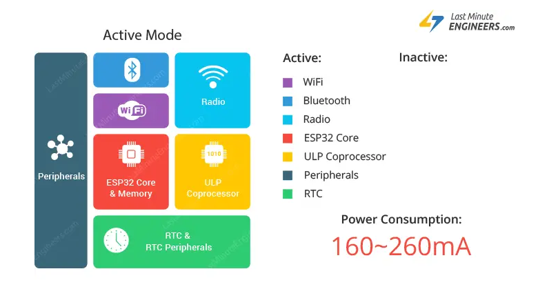
ESP32C6 Sleep Modes
The ESP32C6 documentation indicates that it supports two sleep modes: Light Sleep and Deep Sleep.
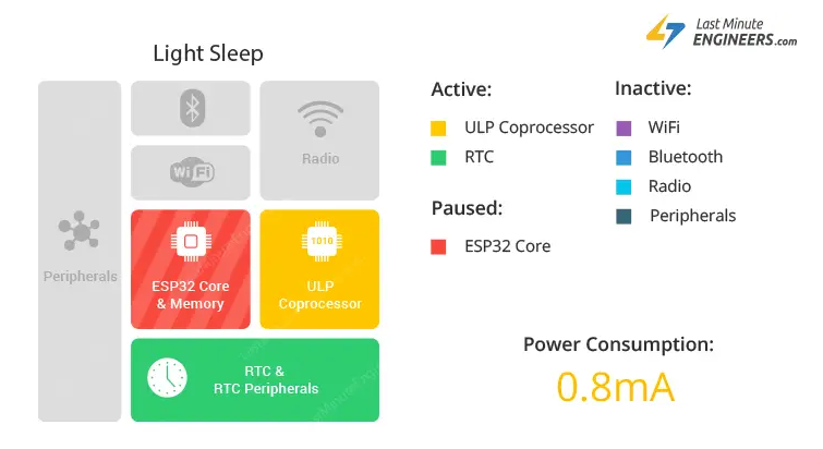
In Light Sleep, the supply voltage and clock of components (RAM, CPU, peripherals, etc.) are limited. However, they are kept in a state that allows them to be reactivated with rapid resumption of execution.
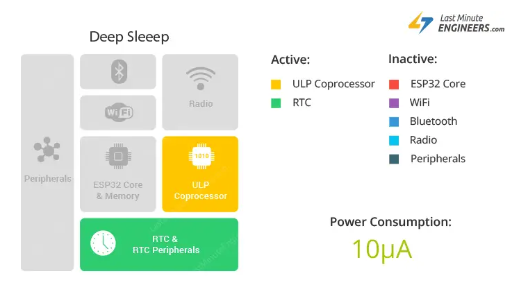
In Deep Sleep, almost all components of the ESP32 are disabled, including the CPU and most peripherals. RAM is also disabled, which means that the program state is not retained.
To optimize the battery life of our sensor, we will put our ESP32C6 into Deep Sleep after each temperature measurement. Note that since the CPU restarts after waking from Deep Sleep, the code in the ‘setup()‘ function of our program will be executed each time we exit Deep Sleep mode.
Source : https://lastminuteengineers.com/esp32-sleep-modes-power-consumption/
Zigbee Sleepy End Device
Our Zigbee device is a Sleepy End Device, meaning it spends most of its time in deep sleep mode and periodically wakes up to communicate. When the ESP32 is in deep sleep mode, the radio is disabled, so it’s important to pay close attention to the timeouts used by Zigbee.
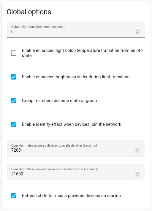
The first timeout to consider is the unavailability timeout on the coordinator side to prevent the sensor from being seen as ‘unavailable’. This timeout is configured in Home Assistant in the Zigbee module settings. By default, this timeout is set to 6 hours (21600 seconds) for battery-powered devices. Since our sensor will communicate every 10 minutes, this delay in the Zigbee coordinator won’t pose a problem for our sensor.
The second timeout to consider is the ‘.ed_timeout‘ parameter in the ESP32’s Zigbee configuration. This parameter specifies that if a Zigbee device is not communicating with the network, it will be considered inactive after this time. This allows the network to maintain an up-to-date list of active devices and free up resources for devices that are no longer present or active. This parameter is configured by default at 64 minutes (ESP_ZB_ED_AGING_TIMEOUT_64MIN) in the ESP32’s Zigbee stack.
The third timeout to consider is the ‘.keep_alive‘ parameter in the ESP32’s Zigbee configuration. A ‘Keep Alive’ message is periodically sent by the ESP32 to the coordinator to signal that it is still active and connected to the network. This parameter is configured by default at 3 seconds in the ESP32’s Zigbee stack. But in the ‘Zigbee_Temp_Hum_Sensor_Sleepy’ example, it’s set to 10 seconds to avoid interference with the data being sent. But I don’t see the use of such a configuration since the Zigbee connection is short (<3 seconds), so I repositioned the default value in my code.
The last delay to consider is the ‘begin timeout’ parameter. This parameter sets the timeout for Zigbee network initialization when the ESP32C6 boots up. After this timeout, the ESP32C6 will consider initialization to have failed and will restart by calling the ‘ESP.restart()’ function. By default, this parameter is set to 30 seconds. It’s reduced to 10 seconds in the ‘Zigbee_Temp_Hum_Sensor_Sleepy‘ example, but I didn’t find this choice relevant. This delay is mainly useful during network initialization. When waking from deep sleep, initialization is normally very fast.
#define ZB_BEGIN_TIMEOUT_DEFAULT 30000  // 30 seconds
#define ZIGBEE_DEFAULT_ED_CONFIG()                                      \
  {                                                                     \
    .esp_zb_role = ESP_ZB_DEVICE_TYPE_ED, .install_code_policy = false, \
    .nwk_cfg = {                                                        \
      .zed_cfg =                                                        \
        {                                                               \
          .ed_timeout = ESP_ZB_ED_AGING_TIMEOUT_64MIN,                  \
          .keep_alive = 3000,                                           \
        },                                                              \
    },                                                                  \
}The program
The following code is heavily inspired by the ‘Zigbee_Temp_Hum_Sensor_Sleepy‘ program given as an example on Espressif’s GitHub. I simply added the BME280 sensor management and battery voltage measurement.
//
// Licensed under the Apache License, Version 2.0 (the "License");
// you may not use this file except in compliance with the License.
// You may obtain a copy of the License at
//
// http://www.apache.org/licenses/LICENSE-2.0
//
// Unless required by applicable law or agreed to in writing, software
// distributed under the License is distributed on an "AS IS" BASIS,
// WITHOUT WARRANTIES OR CONDITIONS OF ANY KIND, either express or implied.
// See the License for the specific language governing permissions and
// limitations under the License.
/**
* @brief Zigbee temperature and humidity sensor Zigbee Sleepy End Device.
*
* https://tutoduino.fr/tutoriels/esp32c6-zigbee/
* This code is based on example "Zigbee temperature and humidity sensor Sleepy device" created by Jan Procházka
* https://github.com/espressif/arduino-esp32/tree/master/libraries/Zigbee/examples/Zigbee_Temp_Hum_Sensor_Sleepy
*/
#ifndef ZIGBEE_MODE_ED
#error "Zigbee end device mode is not selected in Tools->Zigbee mode"
#endif
// Comment or uncomment the following line to display or not debug traces in serial monitor of Arduino IDE
#define DEBUG_TRACE
#include "Zigbee.h"
#include <BME280I2C.h>
#include <Wire.h>
/* Zigbee temperature + humidity sensor configuration */
#define TEMP_SENSOR_ENDPOINT_NUMBER 10
#define uS_TO_S_FACTOR 1000000ULL /* Conversion factor for micro seconds to seconds */
#define TIME_TO_SLEEP 1800 /* Sleep for 30 minutes */
ZigbeeTempSensor zbTempSensor = ZigbeeTempSensor(TEMP_SENSOR_ENDPOINT_NUMBER);
/* BME280 sensor */
BME280I2C sensor;
// 3.7 V Li-Ion battery voltage
const float minVoltage = 3.0;
const float maxVoltage = 4.0;
// Mapp float values to percentage
uint8_t mapFloat(float x, float in_min, float in_max) {
float val;
val = (x - in_min) * (100) / (in_max - in_min);
if (val < 0) {
val = 0;
} else if (val > 100) {
val = 100;
}
return (uint8_t)val;
}
// Get battery voltage en V
float getVbatt() {
uint32_t Vbatt = 0;
for (int i = 0; i < 16; i++) {
Vbatt += analogReadMilliVolts(A0); // Read and accumulate ADC voltage
}
return (2 * Vbatt / 16 / 1000.0); // Adjust for 1:2 divider and convert to volts
}
// Get data from BME280 sensor and go to deep sleep mode
void meausureAndSleep() {
// Measure temperature sensor value
float temperature(NAN), humidity(NAN), pressure(NAN);
uint8_t percentage;
float vBat;
BME280::TempUnit tempUnit(BME280::TempUnit_Celsius);
BME280::PresUnit presUnit(BME280::PresUnit_hPa);
// Read temperature and humidity on BME280 sensor
sensor.read(pressure, temperature, humidity, tempUnit, presUnit);
// Measure battery voltage
vBat = getVbatt();
percentage = mapFloat(vBat, minVoltage, maxVoltage);
#ifdef DEBUG_TRACE
Serial.printf("Battery: %.2fV (%d%%)\n", vBat, percentage);
#endif
// Update battery percentage
zbTempSensor.setBatteryPercentage(percentage);
zbTempSensor.setBatteryVoltage(vBat * 10); // voltage in 100mV
// Update temperature and humidity values in Temperature sensor EP
zbTempSensor.setTemperature(temperature);
zbTempSensor.setHumidity(humidity);
// Report values
zbTempSensor.report();
zbTempSensor.reportBatteryPercentage();
#ifdef DEBUG_TRACE
Serial.printf("Reported temperature: %.2f°C, Humidity: %.2f%%\r\n", temperature, humidity);
#endif
// Turn on the builtin LED for a very short time
flashLED(1);
// Add small delay to allow the data to be sent before going to sleep
delay(500);
// Put device to deep sleep
#ifdef DEBUG_TRACE
Serial.printf("Going to sleep for %d seconds\r\n", TIME_TO_SLEEP);
#endif
esp_deep_sleep_start();
}
// Internal Led flash (n times)
void flashLED(int n) {
for (int i = 0; i < n; i++) {
// Turn on LED for 100ms
digitalWrite(LED_BUILTIN, LOW);
delay(100);
digitalWrite(LED_BUILTIN, HIGH);
delay(200);
}
}
/********************* Arduino functions **************************/
void setup() {
#ifdef DEBUG_TRACE
Serial.begin(115200);
delay(100);
Serial.println();
Serial.println("Tutoduino Zigbee temperature sensor start!");
#endif
// Configure use of external antenna
pinMode(WIFI_ENABLE, OUTPUT); // pinMode(3, OUTPUT);
digitalWrite(WIFI_ENABLE, LOW); // digitalWrite(3, LOW); // Activate RF switch control
delay(100);
pinMode(WIFI_ANT_CONFIG, OUTPUT); // pinMode(14, OUTPUT);
digitalWrite(WIFI_ANT_CONFIG, HIGH); // digitalWrite(14, HIGH); // Use external antenna
// Configure builtin LED and turn it OFF (HIGH)
pinMode(LED_BUILTIN, OUTPUT);
digitalWrite(LED_BUILTIN, HIGH);
// Internal LED flash twice to indicate device start
flashLED(2);
// Init BME280 sensor
Wire.begin();
while (!sensor.begin()) {
#ifdef DEBUG_TRACE
Serial.println("Could not find BME280 sensor!");
#endif
flashLED(3);
delay(1000);
}
// Configure A0 as ADC input for reading battery voltage
pinMode(A0, INPUT);
// Configure the wake up source and set to wake up every 5 seconds
esp_sleep_enable_timer_wakeup(TIME_TO_SLEEP * uS_TO_S_FACTOR);
// Optional: set Zigbee device name and model
zbTempSensor.setManufacturerAndModel("Tutoduino", "ESP32C6TempSensor");
// Set minimum and maximum temperature measurement value
zbTempSensor.setMinMaxValue(-20, 80);
// Set tolerance for temperature measurement in °C (lowest possible value is 0.01°C)
zbTempSensor.setTolerance(1);
// Set power source to battery, battery percentage and battery voltage (now 100% and 3.5V for demonstration)
// The value can be also updated by calling zbTempSensor.setBatteryPercentage(percentage) or zbTempSensor.setBatteryVoltage(voltage) anytime after Zigbee.begin()
zbTempSensor.setPowerSource(ZB_POWER_SOURCE_BATTERY, 100, 35);
// Add humidity cluster to the temperature sensor device with min, max and tolerance values
zbTempSensor.addHumiditySensor(0, 100, 1);
// Add endpoint to Zigbee Core
Zigbee.addEndpoint(&zbTempSensor);
// Create a default Zigbee configuration for End Device
esp_zb_cfg_t zigbeeConfig = ZIGBEE_DEFAULT_ED_CONFIG();
#ifdef DEBUG_TRACE
Serial.println("Starting Zigbee");
#endif
// When all EPs are registered, start Zigbee in End Device mode
if (!Zigbee.begin(&zigbeeConfig, false)) {
// If Zigbee does not start with 30s default timeout (ZB_BEGIN_TIMEOUT_DEFAULT) then restart
flashLED(10);
#ifdef DEBUG_TRACE
Serial.println("Zigbee failed to start!");
Serial.println("Rebooting ESP32!");
#endif
ESP.restart(); // If Zigbee failed to start, reboot the device and try again
}
#ifdef DEBUG_TRACE
Serial.println("Connecting to network");
#endif
while (!Zigbee.connected()) {
#ifdef DEBUG_TRACE
Serial.print(".");
#endif
delay(1000);
flashLED(5);
}
#ifdef DEBUG_TRACE
Serial.println("Successfully connected to Zigbee network");
#endif
// Delay approx 1s (may be adjusted) to allow establishing proper connection with coordinator, needed for sleepy devices
delay(1000);
// Call the function to measure temperature and put the device to deep sleep
meausureAndSleep();
}
void loop() {
// No actions are performed in the loop (the ESP32C6 enters the setup function when it exits deep sleep).
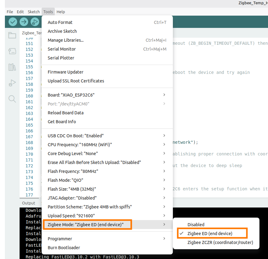
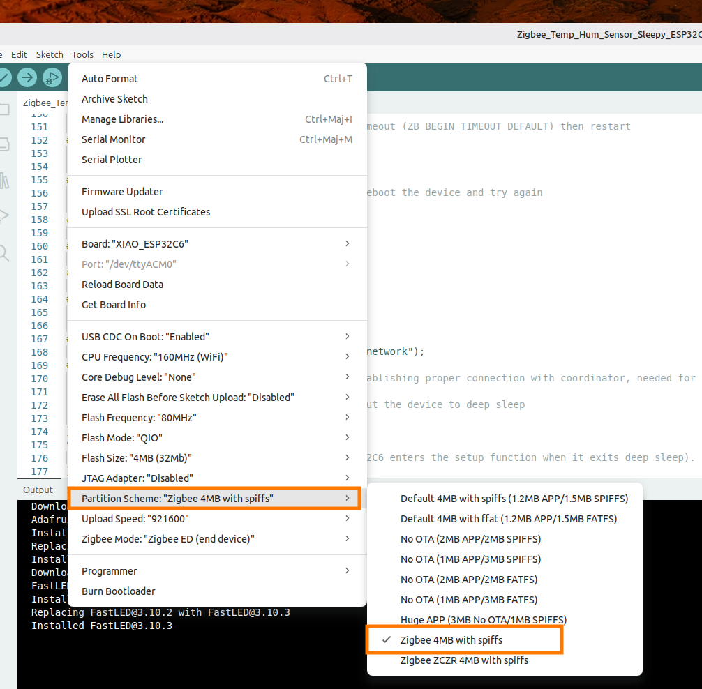
}You have to set 2 parameters before compiling:
- Zigbee Mode: Zigbee End Device
- Partition Scheme: Zigbee 4MB with spiffs
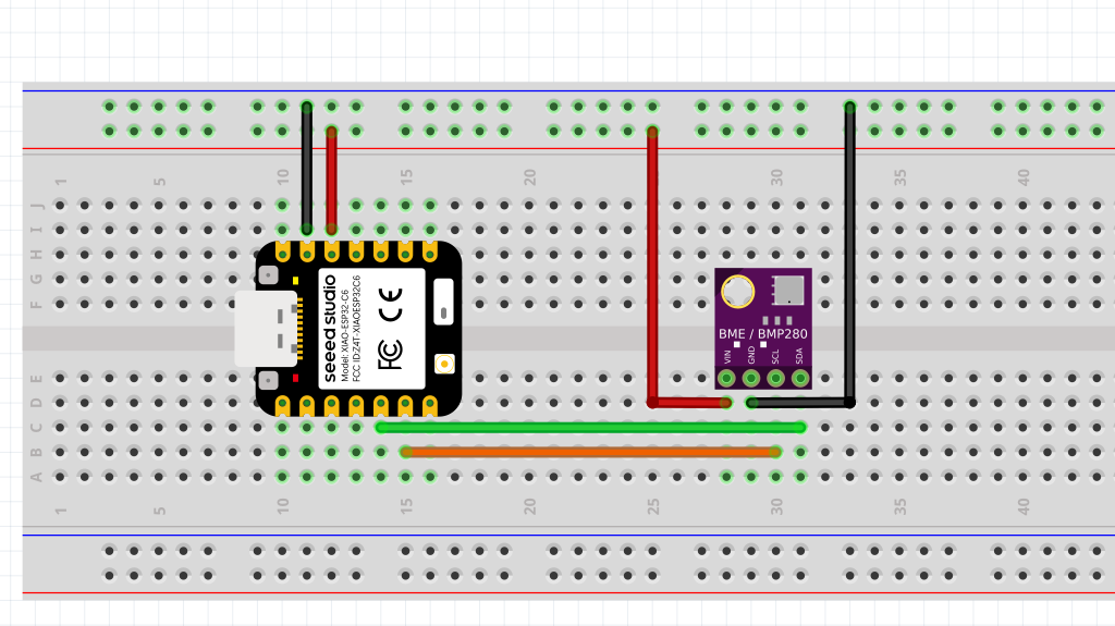
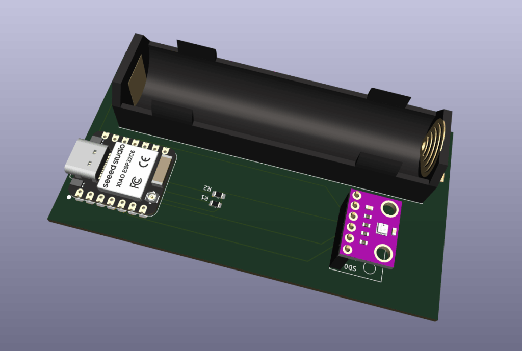
The hardware
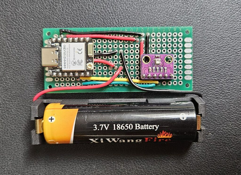
The ESP32C6 is powered by an external 3.7V Li-Ion battery connected to the 2 pins ‘+’ and ‘-‘ on the rear panel of the module.
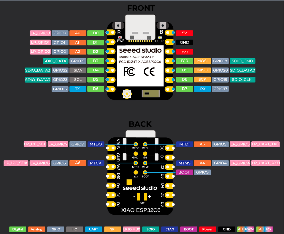

The ESP32C6 is connected to the BME280 sensor via I2C bus (SDA and SCL pins).
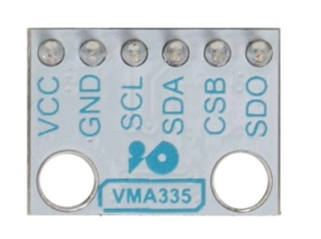
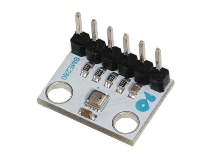
The BME280 sensor is powered by the 3.3V output of the ESP32.
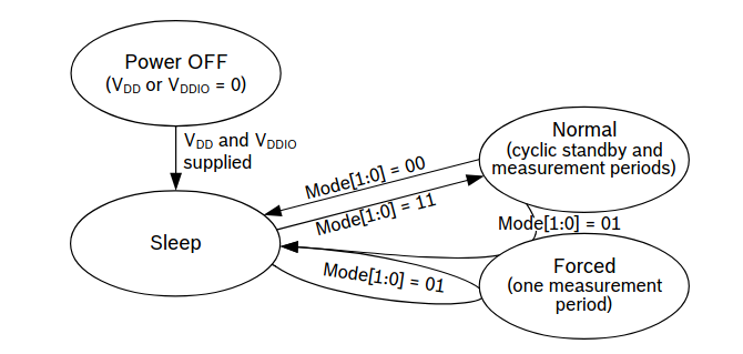
BME280 sensor consumption
To limit power consumption, the sensor must be in standby mode when no measurements are required (ESP32C6 in standby mode). The sensor documentation indicates that it consumes 0.1 μA in standby mode and a few microamps when measuring. However, to minimize power consumption, we configure the sensor in ‘Forced’ mode so that it remains in standby mode when not being polled by the ESP32C6.
The BME280 library used sets the mode to ‘Forced’ in the sensor configuration, so there’s nothing specific to do in our code.
Autonomy
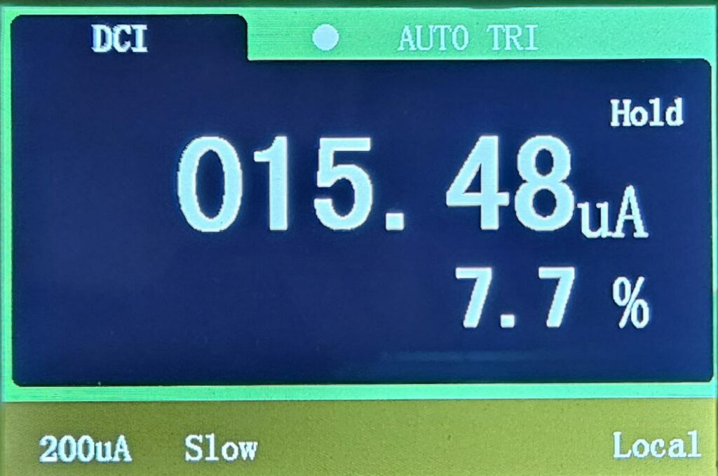
The ESP32C6’s deep sleep power consumption is 15.48 μA, according to the ESP32C6 documentation. In operation (connecting to the Zigbee network and sending data), the device consumes 74 mA (5000 times more than in deep sleep!).
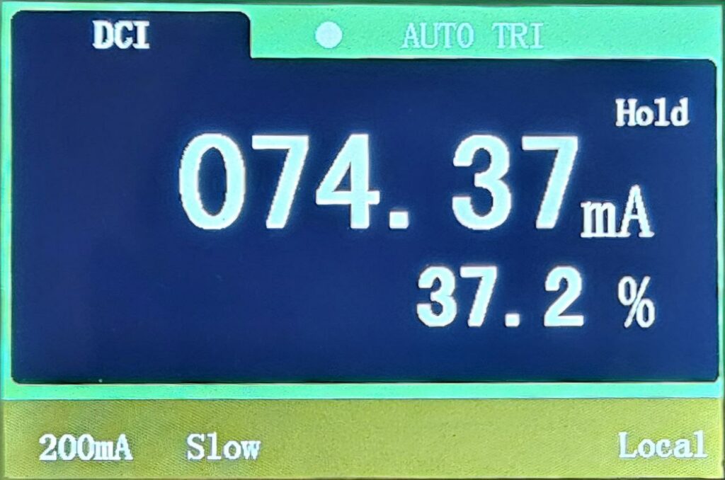
The device remains in deep sleep mode for 10 minutes (600 seconds), goes into active mode for about 3 seconds (the time to connect to the Zigbee network and send data) and then returns to deep sleep mode for 10 minutes.
To calculate the average current consumption of the device, we will use the formula:
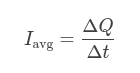
- Calculation of the charge consumed during each period:
- Q1 = I1×t1 = 0,000015×600 = 0,009 C
- Q2 = I2×t2 = 0,064×3 = 0,192 C
- Total charge:
- Qtotal = Q1+Q2 = 0,009+0,192 = 0,201 C
- Average current:
- Iavg = 0,201/603 = 0,000333 A
The average consumption is about 333 μA.
With a 18650 Li-Ion battery having a capacity of approximately 3500 mAh, our sensor should have a battery life of 10500 hours, or 437 days.
Measuring battery voltage
To measure the voltage across the battery terminals, a simple voltage divider bridge made with 220 kΩ resistors allows the battery voltage to be measured on pin A0 (by multiplying by 2 the measurement read on pin A0 because the divider bridge divides the battery voltage by 2).
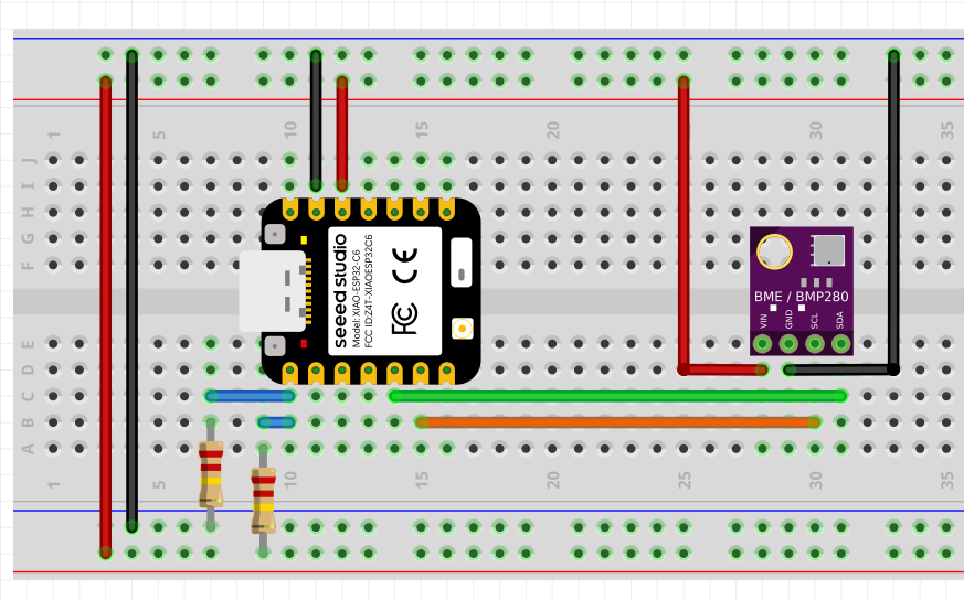
Note: In the diagram above, the voltage divider is shown connected to the ESP32’s 3.3 V output. In practice, it must measure the voltage between the negative (−) and positive (+) terminals of the battery located on the back of the ESP32-C6.
Here is the code inspired by the example for the ESP32C3 which allows to measure the voltage on pin A0 and to transform it into % of battery charge:
  // Function to mapp values to percentage
  float mapFloat(float x, float in_min, float in_max) {
    return (x - in_min) * (100) / (in_max - in_min);
    }
  // Measure battery voltage
  pinMode(A0, INPUT);
  vBat = 2 * analogReadMilliVolts(A0) / 1000.0;
  percentage = (uint8_t) mapFloat(vBat, minVoltage, maxVoltage);
Serial.printf("Battery: %.2fV %d\n", vBat, percentage);Sensor integration into Home Assistant
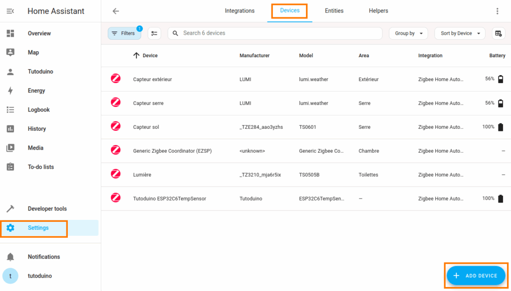
As I mentioned, my home automation system is controlled by Home Assistant on a Raspberry Pi equipped with a Sonoff ZBDongle-E dongle. Integrating the sensor is very simple, by adding a Zigbee device from the ‘Settings’ menu.
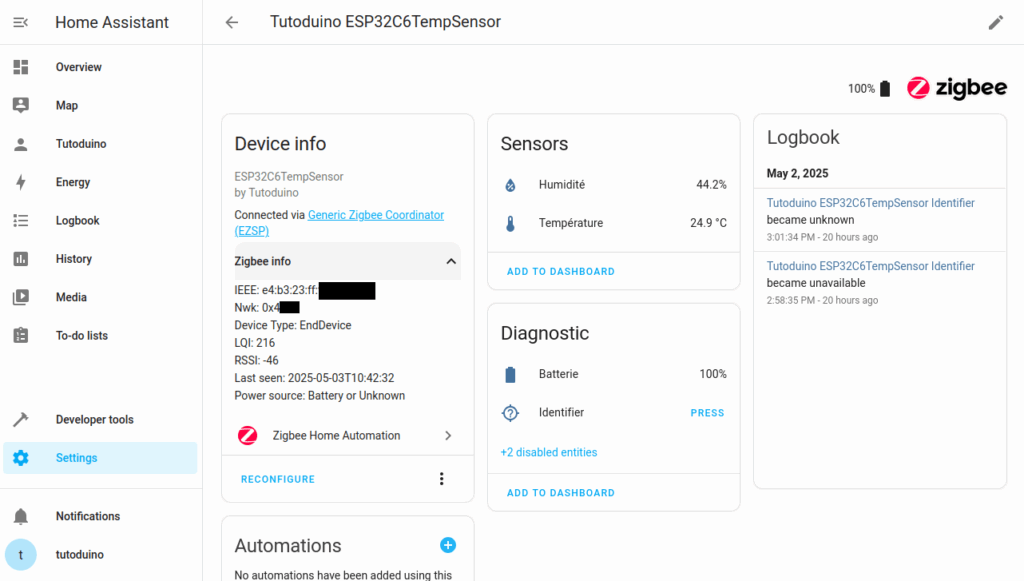
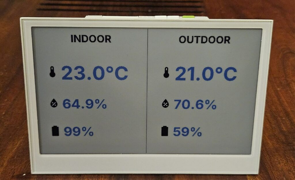
Once added, the sensor appears in the device list. You can clearly see the temperature and humidity measured by the BME280, as well as the battery charge.
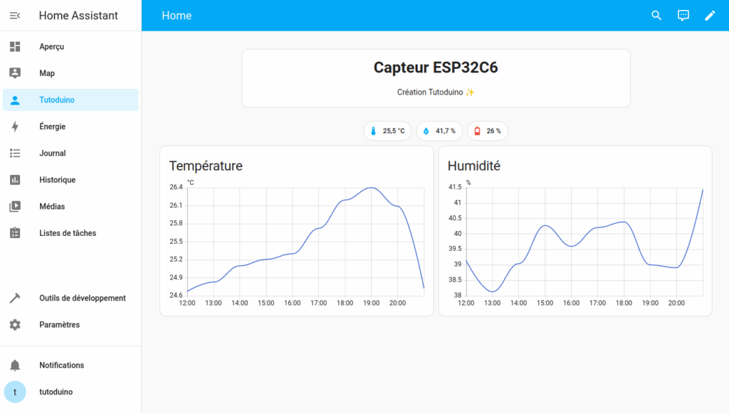
And of course you can organize the sensor visualization as you wish in Home Assistant, here is an example:
Potential Zigbee issue after exiting deep sleep
If all goes well, you should see these traces in the Arduino IDE serial monitor:
08:51:44.105 -> Tutoduino Zigbee temperature sensor start!
08:51:44.105 -> Starting Zigbee
08:51:44.105 -> Connecting to network
08:51:44.105 -> Successfully connected to Zigbee network
08:51:45.105 -> Battery: 4.01V (100%)
08:51:45.105 -> Reported temperature: 24.64°C, Humidity: 45.38%
08:51:45.621 -> Going to sleep nowBut in some cases, exiting deep sleep sometime results in lengthy commissioning times for the Zigbee Sleepy End Device. Traces in the serial monitor indicate that Zigbee fails to start. In such case, the ESP32 reboots after the ‘begin timeout‘ timer (configured to 30s as seen in the timing of the screenshot below).
This issue is usually due to Zigbee limited range. I recommand to pay attention to this problem. Indeed, if it is recurring it strongly impacts the battery life (consumption of 74 mA for almost a minute).
08:46:32.311 -> Tutoduino Zigbee temperature sensor start!
08:46:32.311 -> Starting Zigbee
08:47:02.365 -> Zigbee failed to start!
08:47:02.365 -> ESP-ROM:esp32c6-20220919
08:47:02.365 -> Build:Sep 19 2022
08:47:02.365 -> rst:0xc (SW_CPU),boot:0x1e (SPI_FAST_FLASH_BOOT)
08:47:02.365 -> Saved PC:0x4001975a
08:47:02.365 -> SPIWP:0xee
08:47:02.365 -> mode:DIO, clock div:2
08:47:02.365 -> load:0x40875720,len:0x1260
08:47:02.365 -> load:0x4086c110,len:0xdc4
08:47:02.404 -> load:0x4086e610,len:0x3018
08:47:02.404 -> entry 0x4086c110
08:47:02.718 ->
08:47:02.718 -> Tutoduino Zigbee temperature sensor start!
08:47:02.750 -> Starting Zigbee
08:47:24.940 -> Connecting to network
08:47:24.940 -> Successfully connected to Zigbee network
08:47:25.935 -> Battery: 4.07V (100%)
08:47:25.935 -> Reported temperature: 24.30°C, Humidity: 46.30%
08:47:26.458 -> Going to sleep nowUsing an external antenna on ESP32C6
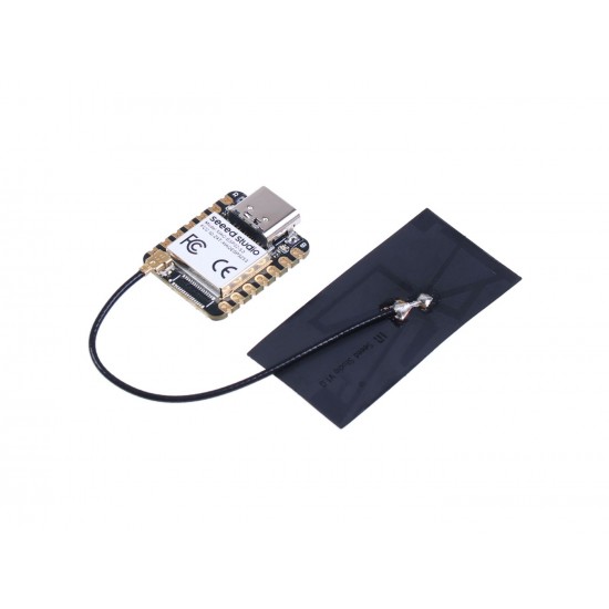
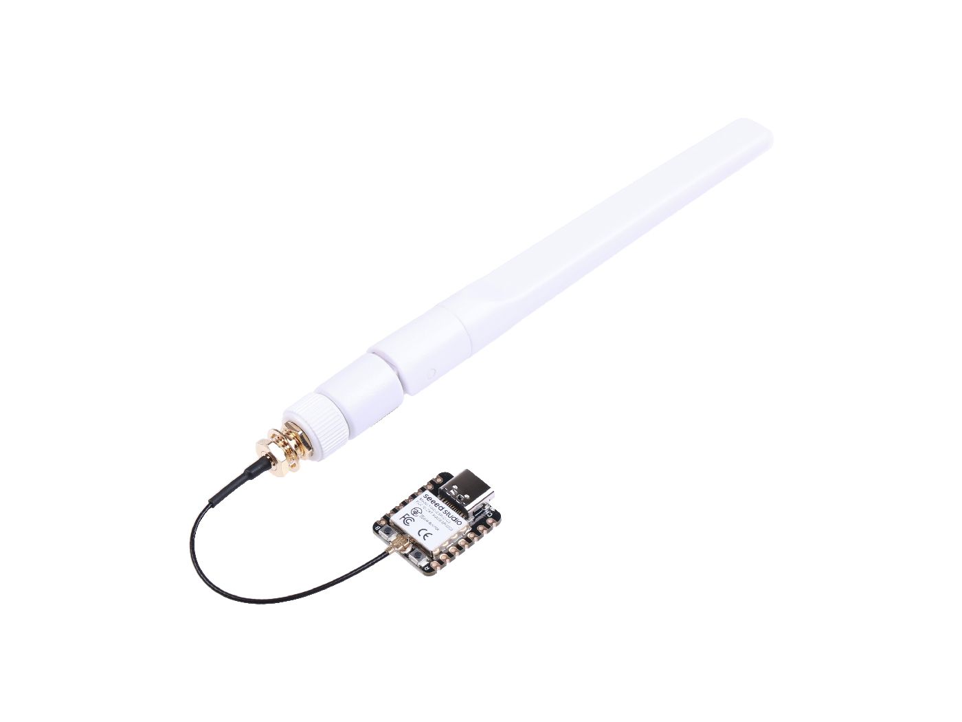
To avoid this type of problem and improve the Zigbee range, I strongly recommend to use an external antenna on the ESP32C6 module, which is connected on its uFL connector. It is a 2.4 GHz antenna, that can be used for Wi-Fi, BLE, Zigbee and Thread.
As explained in ESP32C6 Getting Started page, you have to configure use its external antenna with this code :
// Configure use of external antenna
pinMode(WIFI_ENABLE, OUTPUT); // pinMode(3, OUTPUT);
digitalWrite(WIFI_ENABLE, LOW); // digitalWrite(3, LOW); // Activate RF switch control
delay(100);
pinMode(WIFI_ANT_CONFIG, OUTPUT); // pinMode(14, OUTPUT);
digitalWrite(WIFI_ANT_CONFIG, HIGH); // digitalWrite(14, HIGH); // Use external antennaZigbee Factory Reset
If your sensor is really unable to connect to your Zigbee network, I invite you to follow the following procedure:
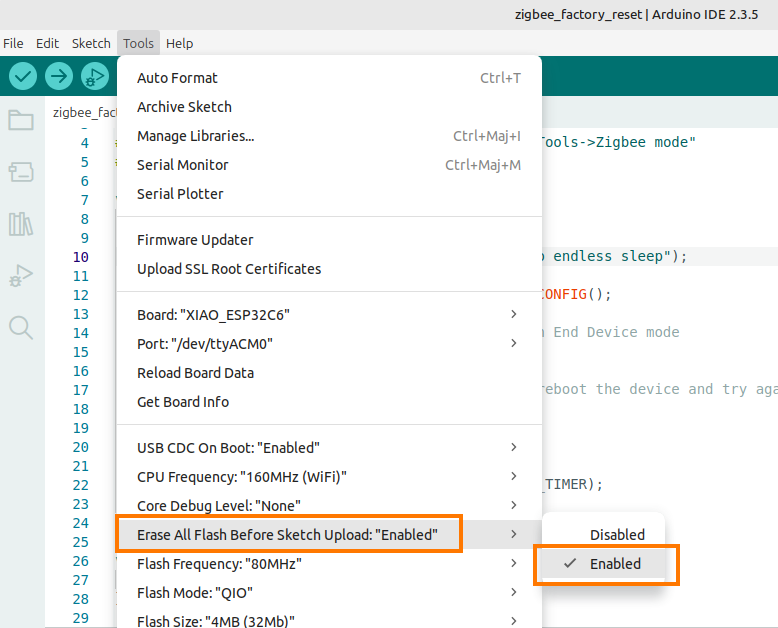
- Set the ‘Erase All Flash Before Sketch Upload’ parameter to ‘Enabled’ in the Arduino IDE.
- Upload the Zigbee factory reset program (code below) to the ESP23C6.
- Unplug the ESP32C6 from the computer, press its ‘BOOT’ button and plug it back in.
- Remove the device from Home Assistant and restart Home Assistant (see restarting the Raspberry Pi).
- Upload the temperature sensor main program sketch.
- Press the ‘RESET’ button on the ESP32C6.
- Repeat the procedure for adding the device in Home Assistant.
This program is used to reset Zigbee to factory settings, it puts the ESP32 into deep sleep indefinitely after the reset is complete. To upload a new program to the ESP32, you must disconnect it from the PC, then hold down its ‘BOOT‘ button while reconnecting it to the PC.
#include "Zigbee.h"
#ifndef ZIGBEE_MODE_ED
#error "Zigbee end device mode is not selected in Tools->Zigbee mode"
#endif
void setup() {
  Serial.begin(115200);
  Serial.println("Zigbee factory reset and going to endless sleep");
  esp_zb_cfg_t zigbeeConfig = ZIGBEE_DEFAULT_ED_CONFIG();
  // When all EPs are registered, start Zigbee in End Device mode
  if (!Zigbee.begin(&zigbeeConfig, false)) {
    Serial.println("Zigbee failed to start!");
    ESP.restart();  // If Zigbee failed to start, reboot the device and try again
  }
  Zigbee.factoryReset(false);
  delay(500);
  esp_sleep_disable_wakeup_source(ESP_SLEEP_WAKEUP_TIMER);
  esp_deep_sleep_start();
}
void loop() {
  // put your main code here, to run repeatedly:
}Modifying the program after adding the device in Home Assistant
It is possible to make changes to the program after adding the sensor in Home Assistant. However, the sensor spends most of its time in deep sleep mode. It is therefore disconnected from the Arduino IDE and it is not possible to upload the program. You must therefore connect the ESP32C6 to the PC while holding down its ‘BOOT‘ button, then upload the program. It should automatically appear in Home Assistant.
If you have enabled the ‘Erase All Flash Before Sketch Upload‘ setting to ‘Enabled‘ in the Arduino IDE before uploading, you must repeat the device addition procedure in Home Assistant. There is no need to delete the device from Home Assistant first.
The final assembly
I made a prototype, it allowed me to validate the code and check the radio range and consumption of the device.
Once the prototype is validated, all that remains is to design the board on KiCad and produce a PCB (coming soon).
If you are using ESPHome to configure your ESP32 devices, I recommand you to read my tutorial ESP32-C6 Temperature Sensor with ESPHome. Though it is connected to Home Assistant Server via Wi-Fi and not Zigbee, its functionnality is similar to the one described above.
To go further, have a look to my tutorial Integrate a reTerminal E1002 into Home Assistant with ESPHome, you will be able to display the data from this sensor in the screen of the reTerminal E1002 e-paper from SeeedStudio.
Sorry for the double-post (you can delete the other). I copied your code and stripped it down to just monitor the battery, but when I was finished, it didn’t want to connect to my Zigbee network [error ” esp_zb_app_signal_handler(): Network steering was not successful (status: ESP_FAIL)”]. If I use one of the very simple Zigbee examples in Arduino IDE like light switch for the built-in LED, I can connect it and control the LED from Home Assistant, so I don’t think I’m missing anything on that front. I’ve copied what I modified to a paste linked below, did I somehow mess something up?
https://pastebin.com/ccqn1jz3
if anyone needs to set and read TX Power.
It can be done like this.
esp_zb_set_tx_power(9);
// read tx_power
int8_t power;
esp_zb_get_tx_power(&power);
Serial.println(power);
Serial.println(“Connecting to network”);
while (!Zigbee.connected()) {
Serial.print(“.”);
delay(100);
}
I have had some Esp32 C5 up and running for a while now.
I think the ESP32 C5 is better than the Xaio C6 because of the higher clock frequency.
Since the task is performed faster when interrupted from deep sleep,
I don’t assume the power consumption is significantly higher.
Spelling mistake it should have been XIAO in my comment.
Hi !
So I need to do something quite different than your deep sleep… I came across this as only site trying to get ESP32 zigbee to work with battery… I would like to create Gas Counter with Zigbee and Hall Sensor (I tried solution with Aquara Door sensor + Reed contact, but it seems that my Gas Meter doesn’t produce enough magnetism to be useful). This is my second try with Magnetic Hall sensor. Problem for me would be even device would be in deep sleep, because it could miss any signals. Would anybody have any idea how to programme for that… Whole idea is that hall sensor is near those numeric wheels, and when wheel is in right position (usually 0), magnetic field increases (from 300 uT to 1600-1800 uT (uT = micro Tesla)) and it sends signal via Zigbee to Home Assistant (or whatever). Any help would be appreciated…
You get a better overview of the trend
when pressure is measured with float,
and a readout with one decimal place.
I have found out how to get the pressure measurement as a float by using the ZigbeeFlowSensor instead of the ZigbeePressureSensor and then adding this to the customize.yaml file
sensor.espressif_zigbee_volume_flow_rate:
state_class: measurement
unit_of_measurement: hPa
device_class: volume_flow_rate
icon: mdi:gauge
friendly_name: Pressure
there should be indent after
sensor.espressif_zigbee_volume_flow_rate:
Does anyone know what the platformio.ini file should look like in pioarduino
for the Tutoduino zigbee example?
With this in the platformio.ini file
it all works with an ESP C5 32E in pioarduino
[env:esp32-c5-devkitc1-n4]
platform = espressif32
board = esp32-c5-devkitc1-n4
framework = arduino
monitor_speed = 115200
#board_build.partitions = custom.csv
board_build.filesystem = littlefs
#board_build.filesystem = spiffs
build_unflags = -DBOARD_HAS_PSRAM
build_flags =
#-D ARDUINO_USB_MODE=0 ; Serial on USBCDC
#-D ARDUINO_USB_CDC_ON_BOOT=0 ; Serial Monitor on Serial0
-DCORE_DEBUG_LEVEL=0
-DZIGBEE_MODE_ED
#-DCORE_DEBUG_LEVEL=5
lib_deps =
I have realized that I can set the time on the DS3231 module
by adding zbTempSensor.addTimeCluster()
You can then quite easily synchronize the time
on the DS3231 module to the coordinator time.
I have posted a version where you can change the
time drift of the DS3231.
By writing to the aging register.
Hai is it possible to send 2 or more data sensor (Humidity and Temperature) to 1 coordinator (Thermostat)?
I have 4 XIAO C6 modules sending data to the same cordinator
starting at the same second with the same interval settings without problems
where I use DS3231 to set the intervals.
If anyone is interested, I can post the code and how I have implemented the DS3231 module, but it probably requires me to explain how to use it since there is limited space for code on the XIAO C6 module.
This is great thanks! Would the same also be possible now in Esphome as yaml? I see they recently added sleepy end device (polling interval) sans light sleep.
Interesting idea!
Done! -> https://tutoduino.fr/en/esp32c6-temperature-esphome/
By the way, I have connected a DS3231 clock module to XIAO C6 which
interrupts at more accurate intervals.
I have posted a new version that is more similar to your version
“https://drive.google.com/drive/folders/1ZjqTTaxRuXrUa8BlCU7KsX9U1jASkrf4?usp=sharing”
since I had Report timeout!
when I used GLOBAL_ON_RESPONSE_CALLBACK
Please delete some of my irrelevant comments
since some are misleading.
I just posted a slightly modified version.
In my first version I forgot to change
float pressure = bme.readPressure()/100;
to
uint16_t pressure = bme.readPressure()/100;
“https://drive.google.com/drive/folders/1ZjqTTaxRuXrUa8BlCU7KsX9U1jASkrf4?usp=sharing”
It is obviously not an error at all when a logpoint is not created.
Home Assistant only creates new points when the new sensor reading is different from the last sensor reading.
I apologize.
So now I just have to figure out how to force Home Assistant to
save a new logpoint even if the sensor reading is the same as the last one sometimes.
I have set my esp32 c6 to log every 5 minutes,
but occasionally it skipped a few logs so that 15 minutes could pass between log points.
I then changed float(temperature) to two decimal places with this
t = String (bme.readTemperature(), 2);
h = String (bme.readHumidity(), 2);
float(temperature) = t.toFloat();
float(humidity) = h.toFloat();
// Update temperature and humidity values in Temperature sensor EP
zbTempSensor.setTemperature(temperature);
zbTempSensor.setHumidity(humidity);
So now it logs exactly every 5 minutes without skipping any.
sorry I was a bit too quick on the trigger.
I still have the problem with missing log points.
Are you using an external antena on your esp32 c6 ?
To investigate it is hard with deep sleep. I used to add some led flash to invetigate, something like :
// Internal LED flash twice to indicate device start
flashLED(2);
// Init BME280 sensor
Wire.begin();
while (!sensor.begin()) {
#ifdef DEBUG_TRACE
Serial.println(“Could not find BME280 sensor!”);
#endif
flashLED(3);
delay(1000);
}
…..
#ifdef DEBUG_TRACE
Serial.println(“Starting Zigbee”);
#endif
// When all EPs are registered, start Zigbee in End Device mode
if (!Zigbee.begin(&zigbeeConfig, false)) {
// If Zigbee does not start with 30s default timeout (ZB_BEGIN_TIMEOUT_DEFAULT) then restart
flashLED(10);
#ifdef DEBUG_TRACE
Serial.println(“Zigbee failed to start!”);
Serial.println(“Rebooting ESP32!”);
#endif
ESP.restart(); // If Zigbee failed to start, reboot the device and try again
}
#ifdef DEBUG_TRACE
Serial.println(“Connecting to network”);
#endif
while (!Zigbee.connected()) {
#ifdef DEBUG_TRACE
Serial.print(“.”);
#endif
delay(1000);
flashLED(5);
}
#ifdef DEBUG_TRACE
Serial.println(“Successfully connected to Zigbee network”);
#endif
// Delay approx 1s (may be adjusted) to allow establishing proper connection with coordinator, needed for sleepy devices
delay(1000);
Thanks for your response
yes I have an external antenna connected.
LQI: 255
RSSI: -30
I just have to continue testing with different settings.
I assume it should be possible to have stable intervals.
Here is a good page from Espressif.
https://docs.espressif.com/projects/arduino-esp32/en/latest/zigbee/ep_temperature_sensor.html
great post
I can’t figure out how to add air pressure.
I need help doing it if possible.
By the way,
I have chosen to use the Adafruit_BME280 library instead
as it seems more updated.
I finally got the air pressure working with the bme280 module,
but unfortunately the zigbee library uses uint16_t pressure_value.
I would have preferred it to be a float value.
Great!
I guess air pressure is in hPa unit so it does not make sense to have is as a float.
If you you copy/paste your code here I could add it in the example.
I’m not entirely sure that the code is error-free and correct.
but maybe you can use it as a basis for your code.
“https://drive.google.com/drive/folders/1ZjqTTaxRuXrUa8BlCU7KsX9U1jASkrf4?usp=sharing”
I just posted a slightly modified version.
“https://drive.google.com/drive/folders/1ZjqTTaxRuXrUa8BlCU7KsX9U1jASkrf4?usp=sharing”
Are you able to read the battery voltage in ha? I created a similar sketch and I also set the voltage. But I am unable to find the value in ha. Also, how often do you receive a value for the battery percentage? My experience is that the value is sent once every couple of hours even though the code explicitly calls the setbatterypercentage every time.
I have battery percentage in ha. I get it usually once value changes.
The ASCII schematic didn’t render correctly
Voltage dividers also drain the battery.
But very little. When 4V in battery and two 220K resistors it will use 0.009mA
Nice app. Here’s a link to my Zigbee Sensor that includes a lot of things to minimize battery use and improve reliability. I have tested a prior more basic version of this using the Seeed C6, but I hate the tiny buttons, so I don’t use them. I use the Adafruit Feather C6. I’ve also tested this on the Olimex H2. The H2 uses less than half the power of the C6
This was derived from a lot of tweaking and testing
https://github.com/def1149/ESP32_Stuff/blob/main/ESP32_C6H2_DeepSleep_Temperature_Sensor_V1_1_08032025.ino
I’d like your comments and feedback.
You can use a low-side MOSFET as a switch to enable/disable the Voltage divider to ground connection, eliminating wasteful battery drain
External mosfet in addition?
Yes, something like this. When control is set high, the divider is active.
Vcc (+) —–[ R1 ]—– Vout
|
[ R2 ]
|
Drain
|
Control —[10kΩ]—- Gate BS170 (N-channel MOSFET)
|
Source
|
GND (-)