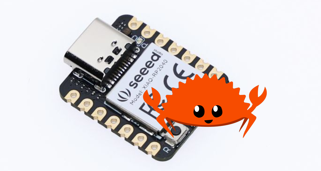
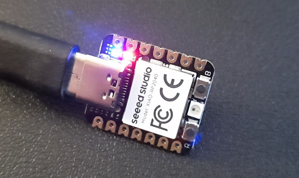
Seeed Studio’s XIAO RP2040 is a miniature board compatible with the Raspberry Pi Pico ecosystem as they use the same RP2040 microcontroller. The Seeed Studio documentation indicates that it is possible to develop with several languages on this board, including C / MicroPython / CircuitPython. We will see in this tutorial that it is also possible to program it in Rust.
Why Rust?
Rust is a programming language developed by Mozilla as a performance and security-oriented alternative to C/C++.
The Rust language has many advantages:
- Safe memory management (weak point of C)
- Good execution performance (weak point of Python)
- Very rich documentation (free online book)
- A user-friendly compiler that gives you suggestions
Install Rust
To install Rust it’s very simple, under Linux just run the following command in a terminal:
curl --proto '=https' --tlsv1.2 -sSf https://sh.rustup.rs | sh
And select the option “1) Proceed with installation (default)” when asked.
Then complete the installation by entering the following command in the terminal:
source "$HOME/.cargo/env"
If you’re on Windows, Rust installation instructions can be found here.
Install Rust support for the RP2040 microcontroller
First make sure you have the latest version of Rust:
rustup self update
rustup update stable
Add the thumbv6m-none-eabi target in the Rust toolchain to enable cross-compilation for RP2040 ARM Cortex-M0+ architecture:
rustup target add thumbv6m-none-eabi
Then install the elf2uf2-rs package which will create the UF2 images for the RP2040 bootloader:
sudo apt install libudev-dev
cargo install elf2uf2-rs
We will use the Workspace rp-hal. This git repository contains a collection of high-level drivers for the RP2040 microcontroller.
git clone https://github.com/rp-rs/rp-hal
Example: seeeduino_xiao_rp2040_blinky
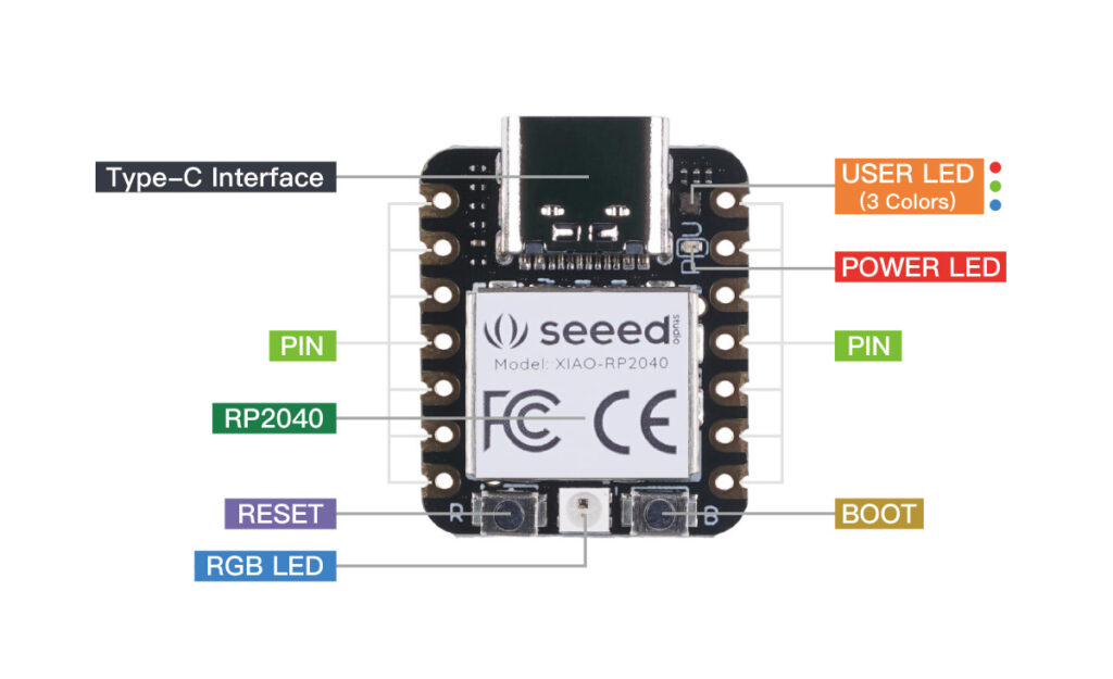
The rp-hal repository contains examples for each microcontroller. To start simply, we will use the seeeduino_xiao_rp2040_blinky example which makes the USER LED of our XIAO RP2040 blink.
First, compile the program:
cd rp-hal
cargo build --example seeeduino_xiao_rp2040_blinky
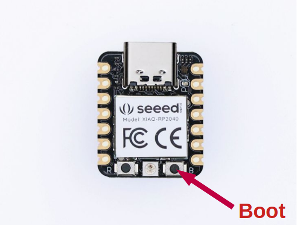
Then you have to download the program to the XIAO RP2040. To do this, connect the XIAO RP2040 card to the PC with a USB cable while pressing the BOOT button. You can then release the button once the cable is connected. The card enters “bootloader” mode and then appears as mass storage.
Once the XIAO RP2040 is seen as a mass storage on your PC (like a USB key), you can start downloading and running the program on the RP2040 with the command:
cargo run --example seeeduino_xiao_rp2040_blinky
If everything goes normally, you should see the program transferred to the XIOA RP2040.
$cargo run --example seeeduino_xiao_rp2040_blinky
    Finished dev [unoptimized + debuginfo] target(s) in 0.11s
     Running `elf2uf2-rs -d target/thumbv6m-none-eabi/debug/examples/seeeduino_xiao_rp2040_blinky`
Found pico uf2 disk /media/tutoduino/RPI-RP2
Transfering program to pico
95.50 KB / 95.50 KB [==================================================================================] 100.00 % 147.52 KB/s
As soon as the transfer is completed, the XIAO RP2040 card will reset and the program will start running.
The seeeduino_xiao_rp2040_blinky program acts on the 3-color USER LED. It makes the LED blinking blue 5 times and then the LED is fading red (0%->100%->0%) using the PWM principle (see my article which explains this principle).
Create your own program
We will now see the different steps that will allow you to create your own program for the XIAO RP2040.
Let’s start by creating a new project named xiao_rp2040_rs using cargo package manager:
cargo new xiao_rp2040_rs
You must then modify the Cargo.toml file to include the dependencies used in your program:
[package]
name = "xiao_rp2040_rs"
version = "0.1.0"
edition = "2021"
description = "XIAO RP2040 RGB LED Blinking"
authors = [
    "Stephane POTIER <tutoduino@gmx.fr>",
    "Thomas POTIER <d34db4b3@protonmail.com>",
]
homepage = "https://tutoduino.fr/en/tutorials/programing-in-rust-the-xiao-rp2040-board/"
license = "MIT OR Apache-2.0"
repository = "https://github.com/rp-rs/rp-hal.git"
[dependencies]
cortex-m = "0.7.6"
seeeduino-xiao-rp2040 = "0.2.0"
panic-halt = "0.2.0"
embedded-hal = "0.2.7"
cortex-m-rt = "0.7"
rp2040-boot2 = "0.2.0"
ws2812-pio = "0.4.0"
smart-leds = "0.3.0"
It is necessary to create the memory.x file in order to describe the layout of the microprocessor memory:
MEMORY {
    BOOT2 : ORIGIN = 0x10000000, LENGTH = 0x100
    FLASH : ORIGIN = 0x10000100, LENGTH = 2048K - 0x100
    RAM   : ORIGIN = 0x20000000, LENGTH = 256K
}

EXTERN(BOOT2_FIRMWARE)

SECTIONS {
    /* ### Boot loader */
    .boot2 ORIGIN(BOOT2) :
    {
        KEEP(*(.boot2));
    } > BOOT2
} INSERT BEFORE .text;
The memory.x file must be placed in the project directory next to the Cargo.toml file:
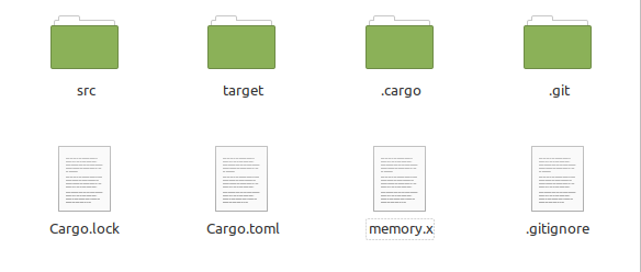
You must then create the .cargo directory and create the .cargo/config.toml file there with the following content:
# set default build target for rp2040
[build]
target = "thumbv6m-none-eabi"
# upload binary to rp2040 instead of running on host
[target.thumbv6m-none-eabi]
runner = "elf2uf2-rs -d"
# use appropriate memory layout
rustflags = ["-C", "link-arg=-Tlink.x"]
All that remains is to finalize our code in the src/main.rs file
//! XIAO RP2040 Blinking LED Example
//!
//! https://tutoduino.fr/
//!
//! Blinks the LED on a Seeed Studio XIAO RP2040 board.
//!
#![no_std]
#![no_main]
use embedded_hal::digital::v2::OutputPin;
use panic_halt as _;
use seeeduino_xiao_rp2040::entry;
use seeeduino_xiao_rp2040::hal;
use seeeduino_xiao_rp2040::hal::pac;
use seeeduino_xiao_rp2040::hal::prelude::*;
/// Entry point to our bare-metal application.
///
/// The `#[entry]` macro ensures the Cortex-M start-up code calls this function
/// as soon as all global variables are initialised.
///
/// The function configures the RP2040 peripherals, then blinks the LED in an
/// infinite loop.
#[entry]
fn main() -> ! {
    // Grab our singleton objects
    let mut pac = pac::Peripherals::take().unwrap();
    let core = pac::CorePeripherals::take().unwrap();
    // Set up the watchdog driver - needed by the clock setup code
    let mut watchdog = hal::Watchdog::new(pac.WATCHDOG);
    // Configure the clocks
    //
    // The default is to generate a 125 MHz system clock
    let clocks = hal::clocks::init_clocks_and_plls(
        seeeduino_xiao_rp2040::XOSC_CRYSTAL_FREQ,
        pac.XOSC,
        pac.CLOCKS,
        pac.PLL_SYS,
        pac.PLL_USB,
        &mut pac.RESETS,
        &mut watchdog,
    )
    .ok()
    .unwrap();
    // The single-cycle I/O block controls our GPIO pins
    let sio = hal::Sio::new(pac.SIO);
    // Set the pins up according to their function on this particular board
    let pins = seeeduino_xiao_rp2040::Pins::new(
        pac.IO_BANK0,
        pac.PADS_BANK0,
        sio.gpio_bank0,
        &mut pac.RESETS,
    );
    // The delay object lets us wait for specified amounts of time (in
    // milliseconds)
    let mut delay = cortex_m::delay::Delay::new(core.SYST, clocks.system_clock.freq().to_Hz());
    // Configure the pins to operate as a push-pull output
    let mut led_blue_pin = pins.led_blue.into_push_pull_output();
    let mut led_green_pin = pins.led_green.into_push_pull_output();
    let mut led_red_pin = pins.led_red.into_push_pull_output();
    // Set green and red led OFF
    led_green_pin.set_high().unwrap();
    led_red_pin.set_high().unwrap();
    loop {
        // Turn on blue LED for 1s
        led_blue_pin.set_low().unwrap();
        delay.delay_ms(1000);
        // Turn off blue LED for 500ms
        led_blue_pin.set_high().unwrap();
        delay.delay_ms(500);
    }
}
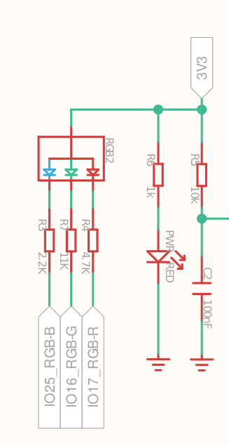
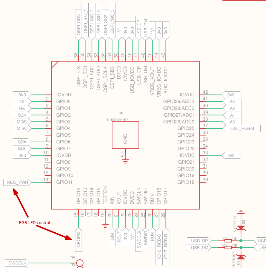
Note: You notice in the code above that the pins of the USER LED 3 colors are set to their low state (set_low) to light up the LED on the XIAO RP2040. The board schematic indeed shows that the RP2040 output pins controlling each color of this LED (IO25_RGB-B, IO16_RGB-G, and IO17_RGB-R) must be driven low for current to flow. More information can be found on the Seeed wiki.
And then as explained for the previous example, connect the USB cable between the PC and the XIAO RP2040 card while pressing the BOOT button.
Then compile and upload (via elf2uf2-rs defined in config.toml) the program to the XIAO RP2040:
cargo run --release
If everything goes normally, you should see the program transferred to 100% and the USER LED flashing blue on the RP2040.
The RGB LED
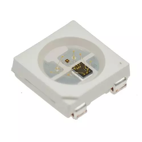
The RGB LED is a WS2812B addressable NeoPixel LED, this is the type of LED that is commonly used in strips.
Principle of NeoPixel LEDs
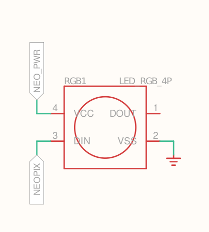
The WS2812B LEDs incorporate an integrated circuit that allows the LEDs to be cascaded using serial communication over one wire. The DOUT pin of each LED being connected to the DIN pin of the next one.
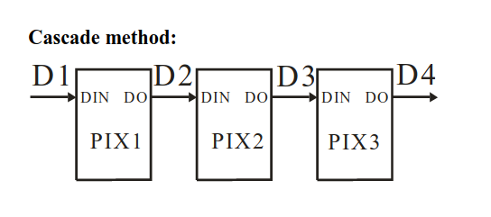
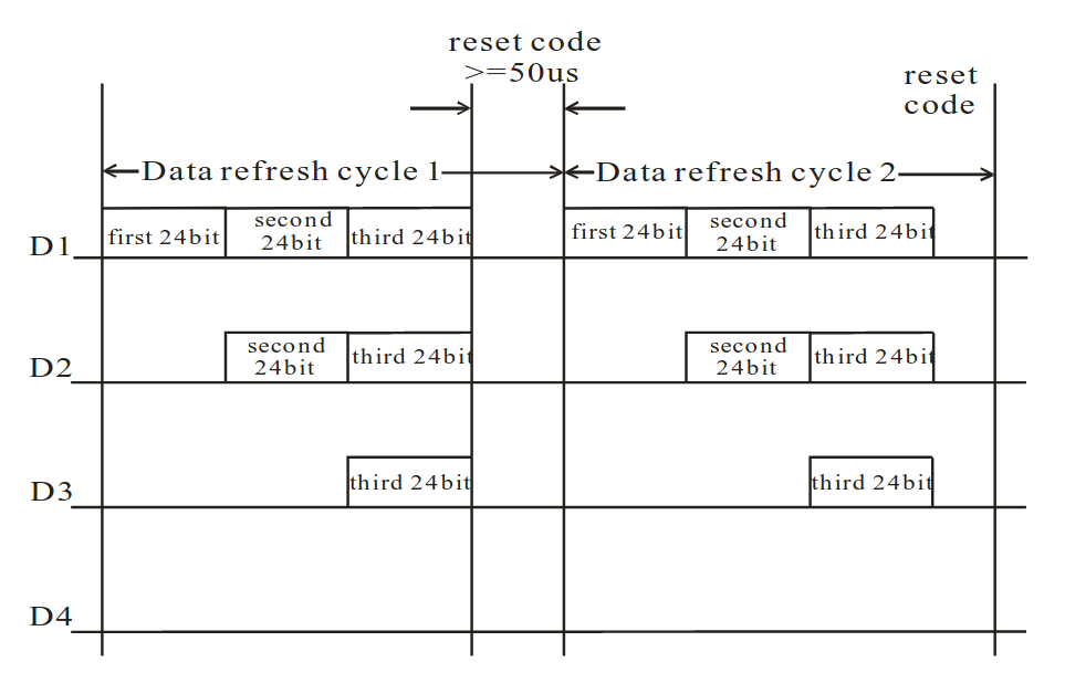
The first LED receives data from the controller on its DIN pin, it takes its color instruction which is coded on the first 3 bytes (RGB color on 24 bits). Then the LED cascades the data to the next LED via its DOUT pin. The second LED receives on its DIN pin its color instruction coded on the first 3 bytes that it receives as well as the color instructions of the following LEDs that it will in turn send via its DOUT pin.
Program controlling USER LED and RGB LED
In our program, we will use the crate ws2812-pio. This driver implements the control of a WS2812 RGB LED strip using PIO of the RP2040 chip.
//! XIAO RP2040 Blinking LED Example
//!
//! https://tutoduino.fr/
//!
//! Blinks the LED on a Seeed Studio XIAO RP2040 board.
//!
#![no_std]
#![no_main]
use embedded_hal::digital::v2::OutputPin;
use hal::pio::PIOExt;
use hal::Timer;
use panic_halt as _;
use seeeduino_xiao_rp2040::entry;
use seeeduino_xiao_rp2040::hal;
use seeeduino_xiao_rp2040::hal::pac;
use seeeduino_xiao_rp2040::hal::prelude::*;
use smart_leds::{SmartLedsWrite, RGB8};
use ws2812_pio::Ws2812;
const RED: RGB8 = RGB8::new(255, 0, 0);
const GREEN: RGB8 = RGB8::new(0, 255, 0);
const BLUE: RGB8 = RGB8::new(0, 0, 255);
const WHITE: RGB8 = RGB8::new(255, 255, 255);
/// Entry point to our bare-metal application.
///
/// The `#[entry]` macro ensures the Cortex-M start-up code calls this function
/// as soon as all global variables are initialised.
///
/// The function configures the RP2040 peripherals, then blinks the LED in an
/// infinite loop.
#[entry]
fn main() -> ! {
    // Grab our singleton objects
    let mut pac = pac::Peripherals::take().unwrap();
    let core = pac::CorePeripherals::take().unwrap();
    // Set up the watchdog driver - needed by the clock setup code
    let mut watchdog = hal::Watchdog::new(pac.WATCHDOG);
    // Configure the clocks
    //
    // The default is to generate a 125 MHz system clock from 12 Mhz crystal
    let clocks = hal::clocks::init_clocks_and_plls(
        seeeduino_xiao_rp2040::XOSC_CRYSTAL_FREQ,
        pac.XOSC,
        pac.CLOCKS,
        pac.PLL_SYS,
        pac.PLL_USB,
        &mut pac.RESETS,
        &mut watchdog,
    )
    .ok()
    .unwrap();
    // The single-cycle I/O block controls our GPIO pins
    let sio = hal::Sio::new(pac.SIO);
    // Set the pins up according to their function on this particular board
    let pins = seeeduino_xiao_rp2040::Pins::new(
        pac.IO_BANK0,
        pac.PADS_BANK0,
        sio.gpio_bank0,
        &mut pac.RESETS,
    );
    // The delay object lets us wait for specified amounts of time (in
    // milliseconds)
    let mut delay = cortex_m::delay::Delay::new(core.SYST, clocks.system_clock.freq().to_Hz());
    let timer = Timer::new(pac.TIMER, &mut pac.RESETS);
    // Setup PIO
    let (mut pio, sm0, _, _, _) = pac.PIO0.split(&mut pac.RESETS);
    // Setup Neopixel RGB LED
    let mut ws = Ws2812::new(
        pins.neopixel_data.into_mode(),
        &mut pio,
        sm0,
        clocks.peripheral_clock.freq(),
        timer.count_down(),
    );
    // Turn on Neopixel RGB LED
    let mut neopixel_power = pins.neopixel_power.into_push_pull_output();
    neopixel_power.set_high().unwrap();
    // Configure the USER LED pins to operate as a push-pull output
    let mut led_blue_pin = pins.led_blue.into_push_pull_output();
    let mut led_green_pin = pins.led_green.into_push_pull_output();
    let mut led_red_pin = pins.led_red.into_push_pull_output();
    loop {
        // Set USER LED to blue
        led_blue_pin.set_low().unwrap();
        led_red_pin.set_high().unwrap();
        led_green_pin.set_high().unwrap();
        // Set RGB LED to blue
        ws.write([BLUE].iter().copied()).unwrap();
        delay.delay_ms(500);
        // Set USER LED to red
        led_blue_pin.set_high().unwrap();
        led_red_pin.set_low().unwrap();
        led_green_pin.set_high().unwrap();
        // Set RGB LED to red
        ws.write([RED].iter().copied()).unwrap();
        delay.delay_ms(500);
        // Set USER LED to green
        led_blue_pin.set_high().unwrap();
        led_red_pin.set_high().unwrap();
        led_green_pin.set_low().unwrap();
        // Set RGB LED to red
        ws.write([GREEN].iter().copied()).unwrap();
        delay.delay_ms(500);
        // Set USER LED to white
        led_blue_pin.set_low().unwrap();
        led_red_pin.set_low().unwrap();
        led_green_pin.set_low().unwrap();
        // Set RGB LED to white
        ws.write([WHITE].iter().copied()).unwrap();
        delay.delay_ms(500);
    }
}
This program is available on my github.
Conclusion
Programming a microcontroller in Rust is relatively simple thanks to the many drivers available. The XIAO RP2040 card offers a very good performance/cost compromise and its reduced size makes it possible to envisage a large number of applications.