You want to measure the air quality inside your home and discover the Raspberry Pi Pico? This tutorial is for you! To measure air quality, we will use the SGP30 sensor. This sensor measures the H2 and Ethanol concentration. The Ethanol concentration makes it possible to measure the level of total volatile organic compounds (TVOC). The level of H2 is used as an indirect indicator and makes it possible to deduce the rate of equivalent CO2 known as eCO2. If the eCO2 cannot be used as a CO2 measurement for a laboratory, it is more than enough to measure the air quality of your interior.
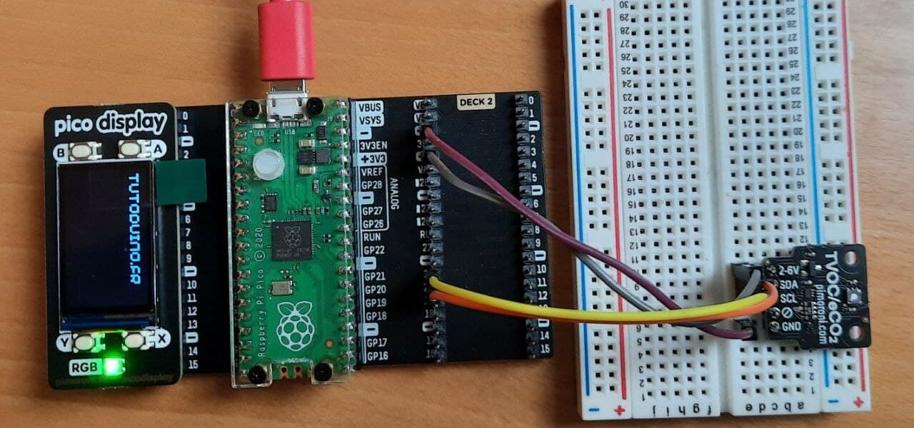
I chose to use the Pi Pico Starter Kit and the pico display LCD screen. Indeed I find it an ideal solution for prototyping projects based on the Raspberry Pi Pico.
The Raspberry Pi Pico
The Raspberry Pi Pico is a micro-controller designed by the Raspberry Foundation. It incorporates an RP040 chip. This micro-controller is particularly interesting because it is at the border between the world of Arduino and that of Raspberry Pi. It has an excellent cost-performance ratio and is very easy to use. The Raspberry Pi Pico can be programmed in Python language or in C/C++.
In this tutorial I will use Python and the Thonny IDE, but be aware that it is possible to use the PlatformIO IDE. PlatformIO is designed for embedded developments and IoT. An interesting discovery for makers!
Before starting…
Before starting our tutorial, we will see how to run a program in Python in the Raspberry Pi Pico.
First, install Thonny, a Python development environment for beginners. For example on Linux Mint (Debian base) just type the following command in the terminal to install it:
sudo apt install thonny
You must then install MicroPython on the Raspberry Pi Pico:
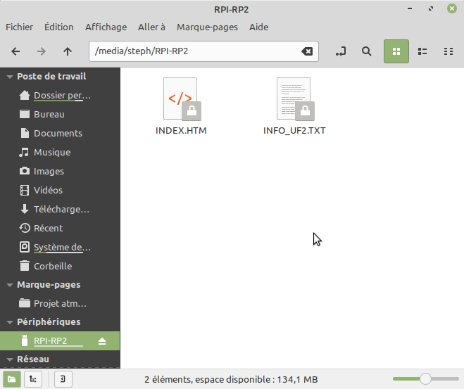
- By default the Raspberry Pi Pico is seen as a USB mass storage (i.e. as a USB key) by the computer. It contains the two files “INDEX.HTM” and “INFO_UF2.TXT”. If not, disconnect the Pico USB cable, press the BOOTSEL button and reconnect the Pico USB cable.
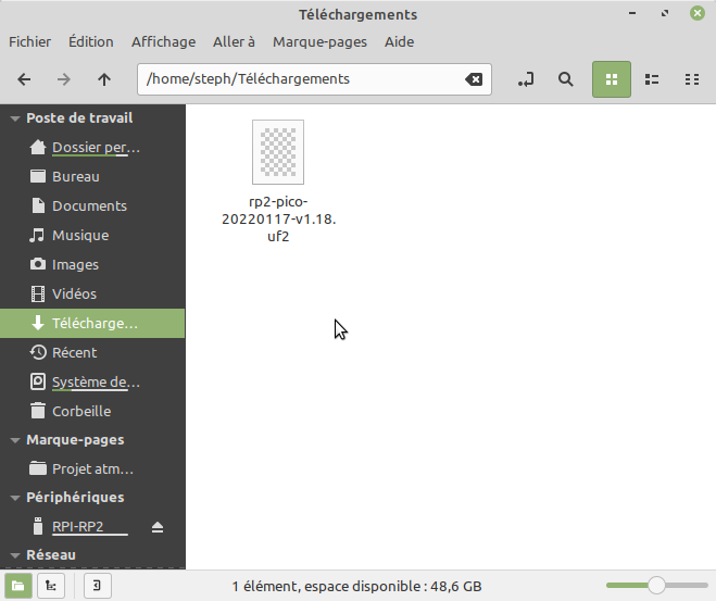
- Download the MicroPython firmware (uf2 format file) for Raspberry Pi Pico from the download page of the site. The UF2 format is intended for flashing a microcontroller connected as a USB mass storage on your PC
- Then simply copy this file to the “RPI-RP2” mass storage to flash MicroPython on the Raspberry Pi Pico.
- The mass storage disappears, as if ejected from the computer. It’s normal, the Raspberry Pi Pico is now seen as a serial port on your computer. This will allow it to communicate with the Thonny development environment.
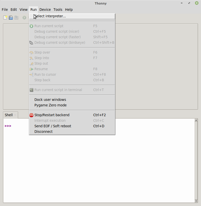
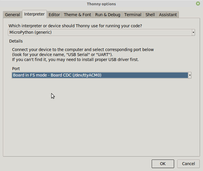
It is now possible to connect the Raspberry Pi Pico to the Thonny IDE. To do this, go to the “Run->Select Interpreter…” menu in Thonny and select the port that has just been activated during the installation of the MicroPython firmware on the Pico.
We will now be able to write our first Python program.
import machine
import utime

led_onboard = machine.Pin(25, machine.Pin.OUT)

while True:
    led_onboard.value(1)
    utime.sleep(1)
    led_onboard.value(0)
    utime.sleep(1)
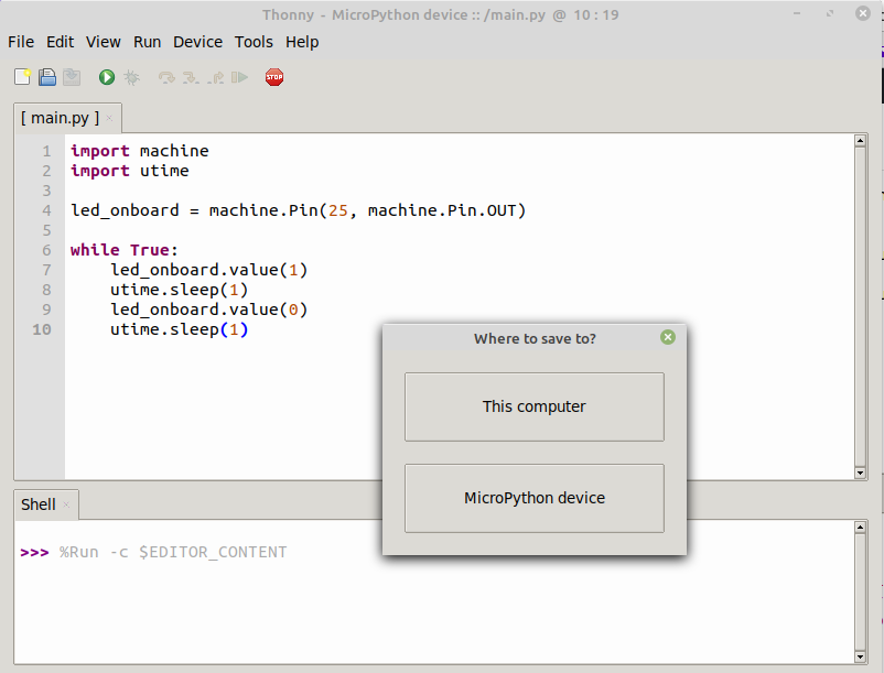
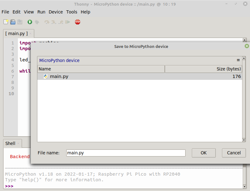
You must then save this program under the name “main.py” on the Pico by clicking on “File->Save as…” then on “MicroPython device”:
Note: if the “Device not connected” error appears, simply do “Run->Stop/Restart backend”. Sometimes it is necessary to unplug and plug the USB cable.
Hardware
To make this tutorial, I use the following equipment:
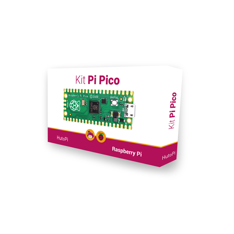
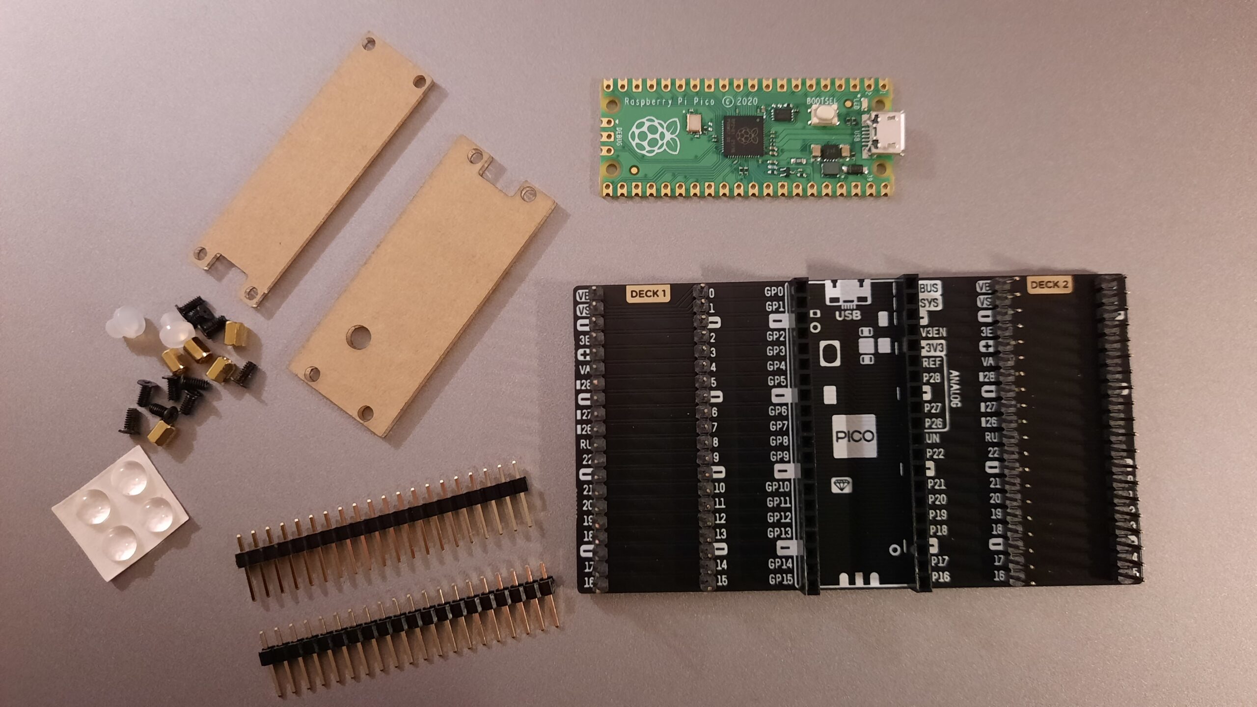
- Starter Kit Pi Pico, a kit containing a Raspberry Pi Pico and an expansion card. It is particularly well suited for prototyping based on the Raspberry Pi Pico
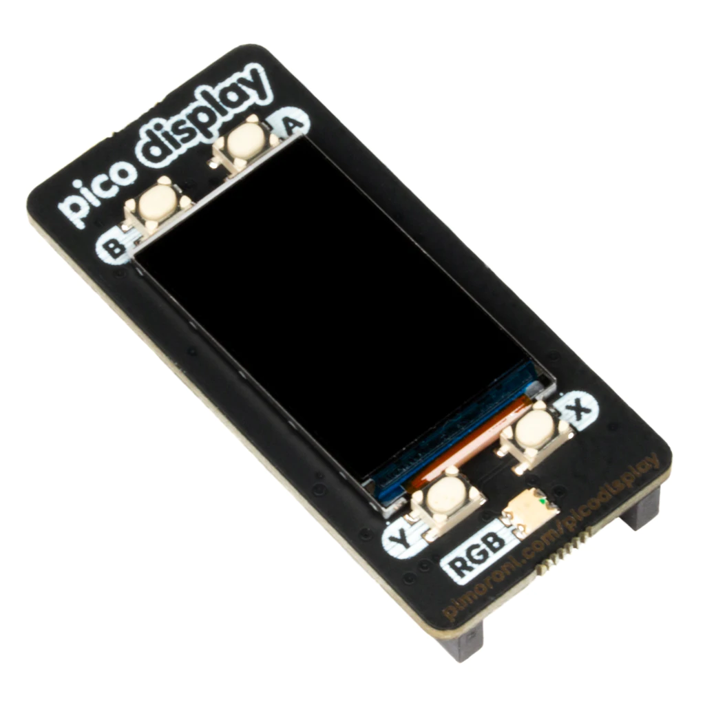
- 1.14″ Pico Display Pack LCD screen, which fits into one of the two “Decks” of the expansion card
- SGP30 Breakout air quality sensor
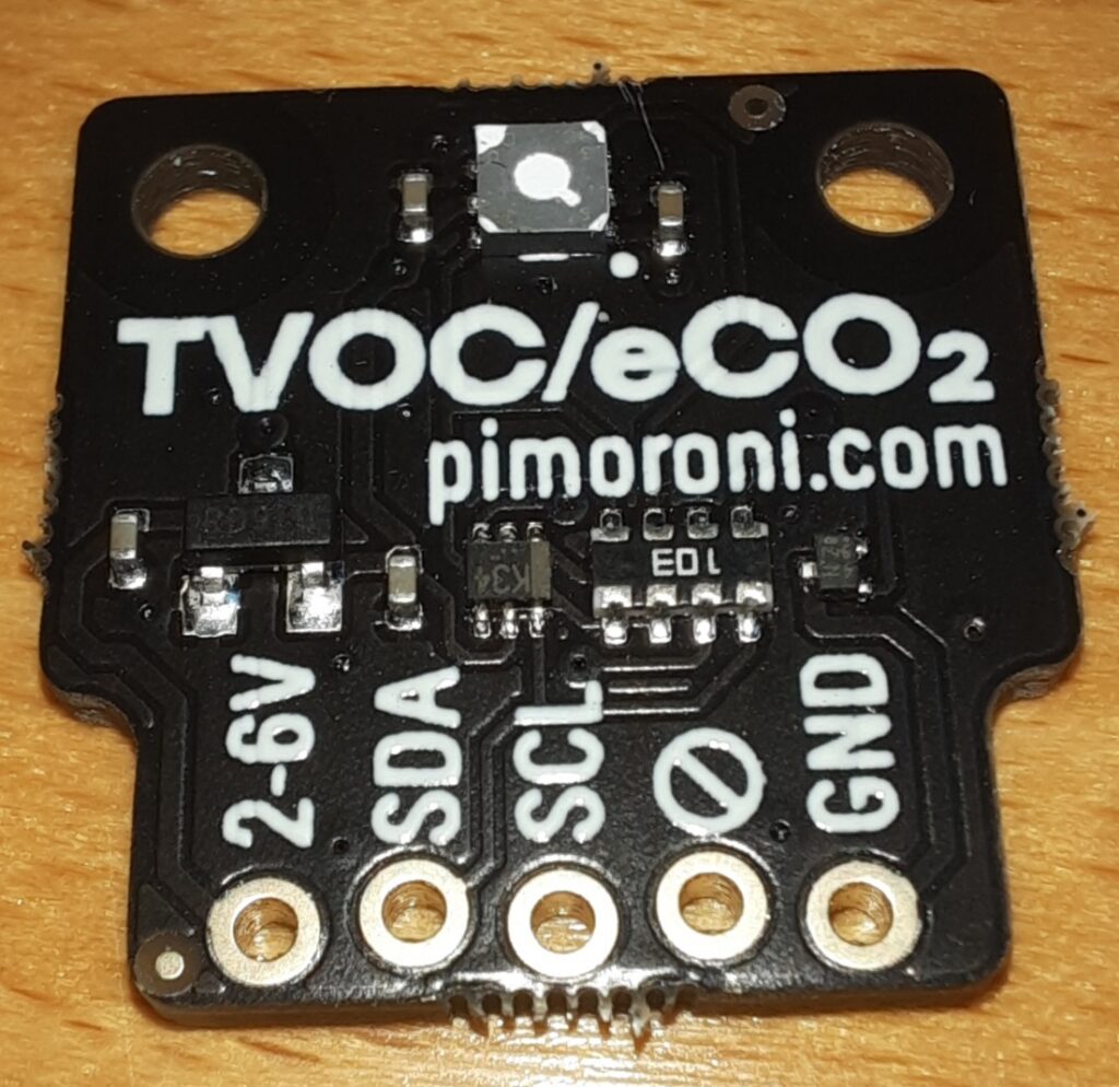
Important! The sensor has a PTFE membrane over it (it looks like a slightly translucent white film). Don’t peel it off! This is a gas-permeable membrane that is required for the sensor to function as intended.
MicroPython firmware provided by Pimoroni
Pimoroni makes available on its GitHub the MicroPython firmware including all the necessary libraries for its products. So just download the latest MicroPython firmware from the GitHub Release space and copy it to the Raspberry Pi Pico.
Use the procedure already used above:
- Unplug the USB cable from the Raspberry Pi Pico
- Press the BOOTSEL button
- Plug in the USB cable of the Raspberry Pi Pico
- Release the BOOTSEL button
- Paste the MicroPython Pimoroni firmware (file in UF2 format) on the USB mass storage “RPI-RP2
Get data from SGP30 sensor
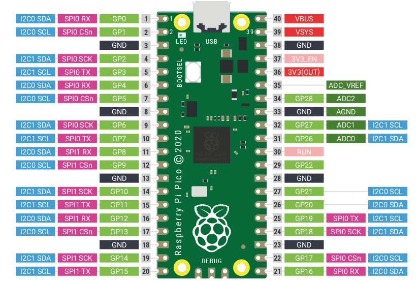
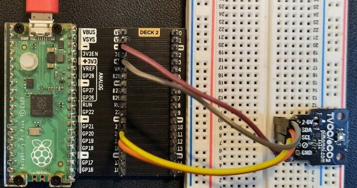
The SGP30 sensor communicates with the Raspberry Pi Pico via the I2C bus. It is therefore necessary to connect the SDA and SCL pins of the sensors to the corresponding pins on the Raspberry Pi Pico.
The Raspberry Pi Pico allows you to configure several I2C interfaces, we choose to use the first (I2C0). The GP21 pin (27) corresponds to the SCL and the GP20 pin (26) to the SDA.
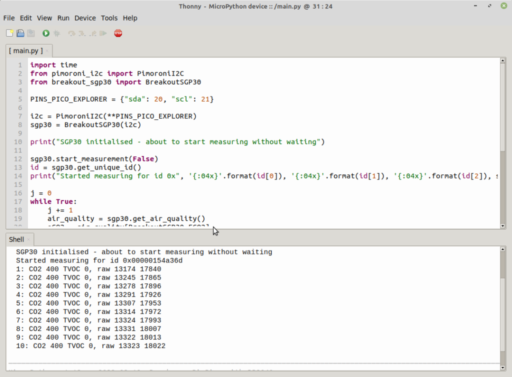
The Python code available on Pimoroni’s GitHub allows the values reported by the sensor to be displayed on the Thonny Shell:
import time
from pimoroni_i2c import PimoroniI2C
from breakout_sgp30 import BreakoutSGP30

PINS_PICO_EXPLORER = {"sda": 20, "scl": 21}

i2c = PimoroniI2C(**PINS_PICO_EXPLORER)
sgp30 = BreakoutSGP30(i2c)

print("SGP30 initialised - about to start measuring without waiting")

sgp30.start_measurement(False)
id = sgp30.get_unique_id()
print("Started measuring for id 0x", '{:04x}'.format(id[0]), '{:04x}'.format(id[1]), '{:04x}'.format(id[2]), sep="")

j = 0
while True:
    j += 1
    air_quality = sgp30.get_air_quality()
    eCO2 = air_quality[BreakoutSGP30.ECO2]
    TVOC = air_quality[BreakoutSGP30.TVOC]

    air_quality_raw = sgp30.get_air_quality_raw()
    H2 = air_quality_raw[BreakoutSGP30.H2]
    ETHANOL = air_quality_raw[BreakoutSGP30.ETHANOL]

    print(j, ": CO2 ", eCO2, " TVOC ", TVOC, ", raw ", H2, " ", ETHANOL, sep="")
    if j == 30:
        print("Resetting device")
        sgp30.soft_reset()
        time.sleep(0.5)
        print("Restarting measurement, waiting 15 secs before returning")
        sgp30.start_measurement(True)
        print("Measurement restarted, now read every second")

    time.sleep(1.0)
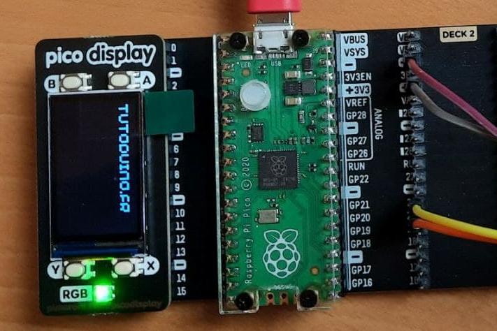
Display on the pico display
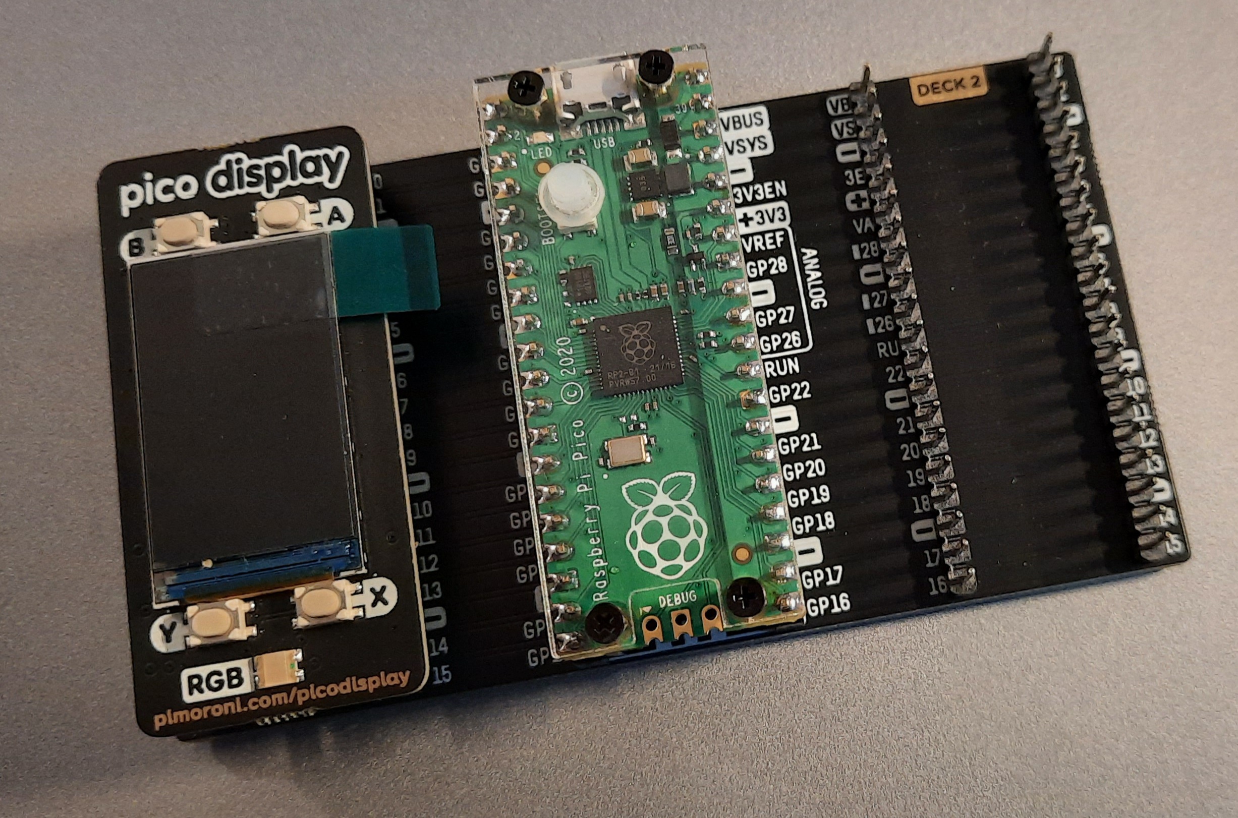
The pico display is intended to be installed directly on the back of the Raspberry Pi Pico. But in our tutorial we will install it on the “DECK 1” of the expansion card.
The following example is provided by Pimoroni. It displays the name of the button that is pressed on the pico display.
# This example shows you a simple, non-interrupt way of reading Pico Display's buttons with a loop that checks to see if buttons are pressed.

import picodisplay as display  # Comment this line out to use PicoDisplay2
import utime

# Initialise display with a bytearray display buffer
buf = bytearray(display.get_width() * display.get_height() * 2)
display.init(buf)
display.set_backlight(0.5)


# sets up a handy function we can call to clear the screen
def clear():
    display.set_pen(0, 0, 0)
    display.clear()
    display.update()


while True:
    if display.is_pressed(display.BUTTON_A):              # if a button press is detected then...
        clear()                                           # clear to black
        display.set_pen(255, 255, 255)                    # change the pen colour
        display.text("Button A pressed", 10, 10, 240, 4)  # display some text on the screen
        display.update()                                  # update the display
        utime.sleep(1)                                    # pause for a sec
        clear()                                           # clear to black again
    elif display.is_pressed(display.BUTTON_B):
        clear()
        display.set_pen(0, 255, 255)
        display.text("Button B pressed", 10, 10, 240, 4)
        display.update()
        utime.sleep(1)
        clear()
    elif display.is_pressed(display.BUTTON_X):
        clear()
        display.set_pen(255, 0, 255)
        display.text("Button X pressed", 10, 10, 240, 4)
        display.update()
        utime.sleep(1)
        clear()
    elif display.is_pressed(display.BUTTON_Y):
        clear()
        display.set_pen(255, 255, 0)
        display.text("Button Y pressed", 10, 10, 240, 4)
        display.update()
        utime.sleep(1)
        clear()
    else:
        display.set_pen(255, 0, 0)
        display.text("Press any button!", 10, 10, 240, 4)
        display.update()
    utime.sleep(0.1)  # this number is how frequently the Pico checks for button presses
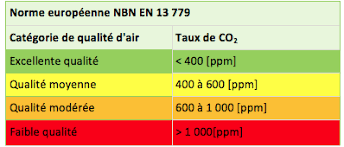
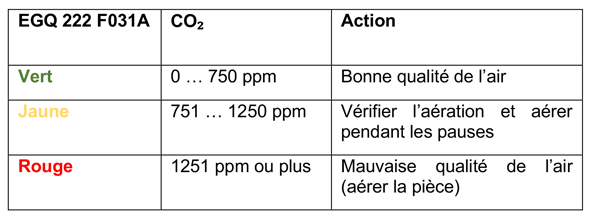
CO2 levels and air quality
Several standards define air quality according to the concentration of CO2. It is difficult to find consistent sources and access to standards is paid (!).
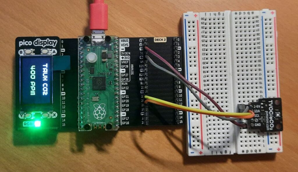
The color of the pico display LED will depend on the level of CO2. In my program, I decided to use the following values for the correspondence between the CO2 level and the color of the LED:
- 0..499 ppm -> Air quality is good, the LED will be green
- 500..999 ppm -> Air quality is average, LED will be Orange
- = 1000 ppm -> The air quality is poor, the LED will be Red
The software
Our program will read the CO2 level in the air from the sensor and display it on the LCD screen of the pico display.
# Tutoduino.fr
# Mesurez la qualite de l'air interieur avec un Raspberry Pi Pico

import picodisplay as display
import utime
from pimoroni_i2c import PimoroniI2C
from breakout_sgp30 import BreakoutSGP30

# Fonction qui retourne le niveau de CO2 et TVOC
def mesure_capteur():
    air_quality = sgp30.get_air_quality()
    eCO2 = air_quality[BreakoutSGP30.ECO2]
    TVOC = air_quality[BreakoutSGP30.TVOC]
    return eCO2, TVOC

# Fonction qui efface l'ecran
def clear():
    display.set_pen(0, 0, 0)
    display.clear()
    display.update()

# Gere la couleur en fonction du niveau de CO2
def get_color(CO2):
    if eCO2 < 500:
        return 0,0xff,0 #vert
    elif eCO2 < 1000:
        return 0xff,165,0 #orange
    else:
        return 0xff,0,0 #rouge

# Initilisation de l'ecran
buf = bytearray(display.get_width() * display.get_height() * 2)
display.init(buf)
display.set_backlight(0.5)

# Initialisation du capteur
PINS_PICO_EXPLORER = {"sda": 20, "scl": 21}
i2c = PimoroniI2C(**PINS_PICO_EXPLORER)
sgp30 = BreakoutSGP30(i2c)
sgp30.soft_reset()
utime.sleep(1)
sgp30.start_measurement(False)

# Boucle du programme principal
while True:
    # Lecture de la qualite de l'air sur le capteur
    eCO2, TVOC = mesure_capteur()
    print("CO2 ", eCO2, " TVOC ", TVOC)
    r,g,b = get_color(eCO2)
    # Affichage sur l'ecran
    display.set_pen(0xff,0xff,0xff)
    display.text("Taux CO2", 30, 10, 240, 4)
    display.set_pen(r,g,b)
    display.text("{}".format(eCO2) + " ppm", 40, 70, 240, 4)
    display.set_led(r,g,b)
    display.update()
    utime.sleep(1)
    clear()
Hi
I downloaded the latest pimoroni-micropython (https://github.com/pimoroni/pimoroni-pico/releases/download/v1.20.2/pimoroni-pico-v1.20.2-micropython.uf2). But when i try to run the code, i get always the following Error: ImportError: no module named ‘picodisplay’
What am I doing wrong?
Hello, a bit late, but it seems Pimoroni has a new API for displays since June 2022: picographics
https://github.com/pimoroni/pimoroni-pico/releases/tag/v1.19.0
I haven’t tried to update the code since I don’t have a Pico Display but it should be pretty straigthforward.
Hello,
How to include the libraries BreakoutSGP30 and pimoroni I2C ? where or how to find these python files to included in the library for importing?
Thank you
Hello, if you follow the procedure described in chapter “MicroPython firmware provided by Pimoroni”, all libraries should be included. It does not work ?