In a previous tutorial, I explained how to create a Zigbee temperature sensor based on ESP32C6 and how to integrate it into Home Assistant.
In this new tutorial, I guide you through integrating a Seeed Studio reTerminal E1002 e-paper display into Home Assistant to display data from this sensor.
We will use the ESPHome framework, which greatly simplifies integrating the reTerminal display into Home Assistant via a simple YAML configuration. This configuration allows precise description of peripherals connected to the ESP32-S3 microcontroller (display, buttons, buzzer, LED, etc.), as well as actions to be executed locally. ESPHome then compiles this YAML file to generate firmware that is uploaded to the reTerminal.
Introducing the reTerminal
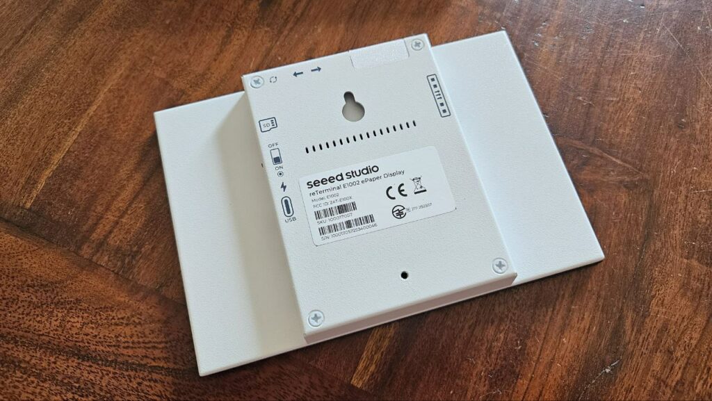
The reTerminal E1002 is a ready-to-use device featuring a robust metal case housing a 7.3″ color e-paper display with a resolution of 800×480. It is powered by an ESP32-S3 microcontroller and includes 3 buttons, a buzzer, a status LED (in addition to the power LED), a temperature and pressure sensor, a microphone, and a MicroSD card reader. It is powered by an internal 2000 mAh battery providing up to 3 months of autonomy.
The detailed specifications of the reTerminal E1002 as well as its quick start guide are available on the Seeed Studio wiki.
Key features include:
- A 7.3-inch full-color ePaper display with 800×480 resolution using Advanced Color ePaper (ACeP) technology with 6 colors (including black and white).
- Powered by the Espressif ESP32-S3 microcontroller with 8MB PSRAM.
- 32MB SPI flash memory and a MicroSD card slot supporting up to 32GB (FAT32 format).
- Wireless connectivity with 2.4GHz 802.11 b/g/n Wi-Fi and Bluetooth 5.0.
- Integrated temperature and humidity sensor (SHT40), microphone, buzzer, and multiple buttons.
- A built-in 2000 mAh battery providing up to 3 months of battery life.
- Multiple LEDs including a green status LED and a red charging LED.
- USB-C port for charging and firmware updates.
- An 8-pin expansion header exposing ESP32-S3 GPIOs, I2C, UART, ADC, and power lines for additional hardware expansion.
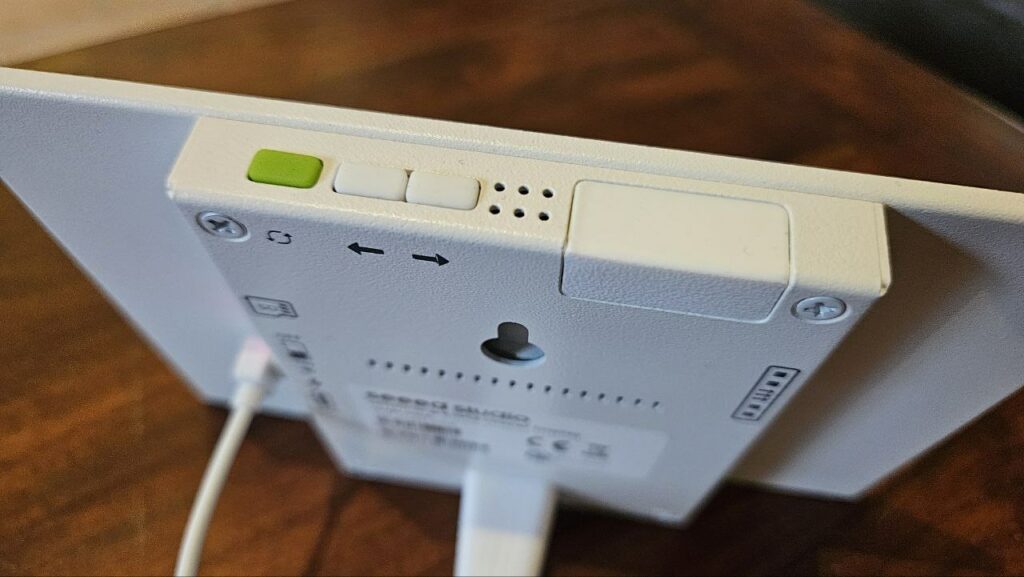
The device comes with a power switch on the back and supports easy network setup via Wi-Fi (2.4 GHz only) through hotspot or mobile app configuration. It can connect to the SenseCraft HMI platform for no-code UI dashboard creation and also supports Home Assistant, Arduino, and ESP-IDF environments for more advanced development.
The wiki offers comprehensive instructions on getting started, powering the device on, network configuration, Bluetooth setup, dashboard creation using the SenseCraft platform, device operation, troubleshooting, and hardware expansion options.


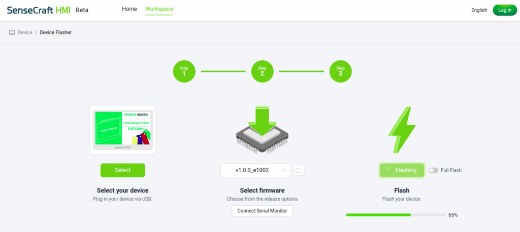
Updating the reTerminal firmware
It is recommended to install the latest available firmware as soon as you first use your device. After creating your user account on the sensecraft.seeed.cc website, connect your reTerminal to a USB port on your computer, then use the Device Flasher tool to flash the most recent firmware.
In this tutorial, SenseCraft HMI will not be used: therefore it is not necessary to follow the procedure displayed on the reTerminal screen, nor to connect to the Wi-Fi hotspot it broadcasts. The goal here is to make the reTerminal work with Home Assistant by configuring it directly through the ESPHome framework.
Configuring reTerminal with ESPHome
To install the ESPHome Device Builder add-on on your Home Assistant server and start it, follow these steps:
- In Home Assistant, go to Settings > Add-on Store.
- Search for ESPHome in the add-on list.
- Click on ESPHome Device Builder and then Install.
- Wait until the installation completes.
- Once installed, click Start to launch the add-on.
- Optionally, open the add-on’s Web UI to begin creating and managing your ESPHome device configurations.
This add-on provides a simple web interface to build, compile, and upload ESPHome firmware to your devices directly from Home Assistant.

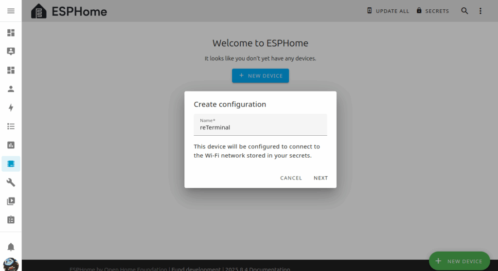
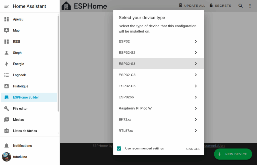
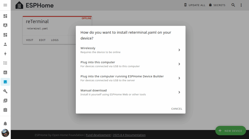
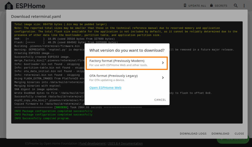
In the ESPHome Builder module, add the reTerminal as a new device of type ESP32-S3. Since the reTerminal is not yet configured to join the Wi-Fi network and Home Assistant is running over HTTP (not HTTPS), direct firmware upload from ESPHome Builder is not possible. Instead, use the Manual Download option to retrieve the compiled firmware in Factory format (Previously Modern).
Note: Installing tools and compiling the firmware can be relatively slow, especially if Home Assistant is hosted on a less powerful Raspberry Pi. It is not uncommon for each compilation to take several minutes.
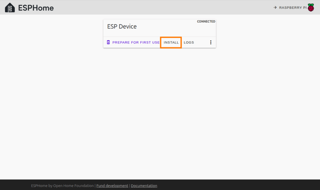
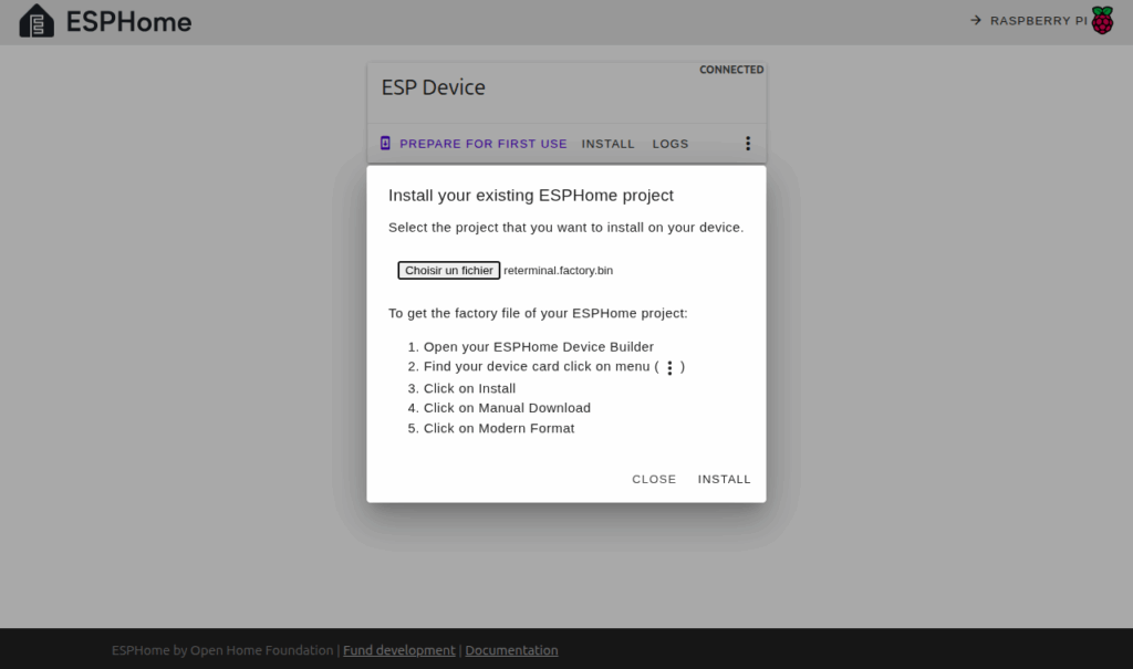
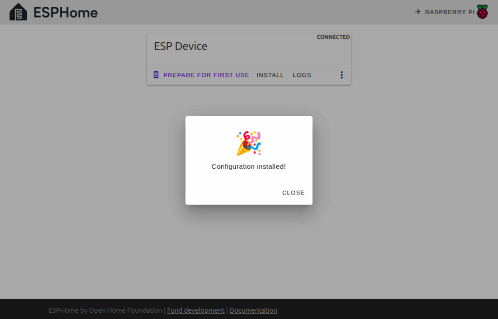
Then upload this firmware file to the reTerminal using the ESPHome online tool. After this initial flashing, the reTerminal will connect to your Wi-Fi network. Future firmware updates can then be done directly over Wi-Fi from Home Assistant without the need for a wired connection.
Hello World!
We will now create an example to help you understand the principle of ESPHome and the configuration of the reTerminal. In this example, we will simply display the message Hello World! on the reTerminal screen.
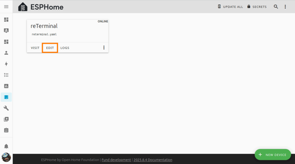
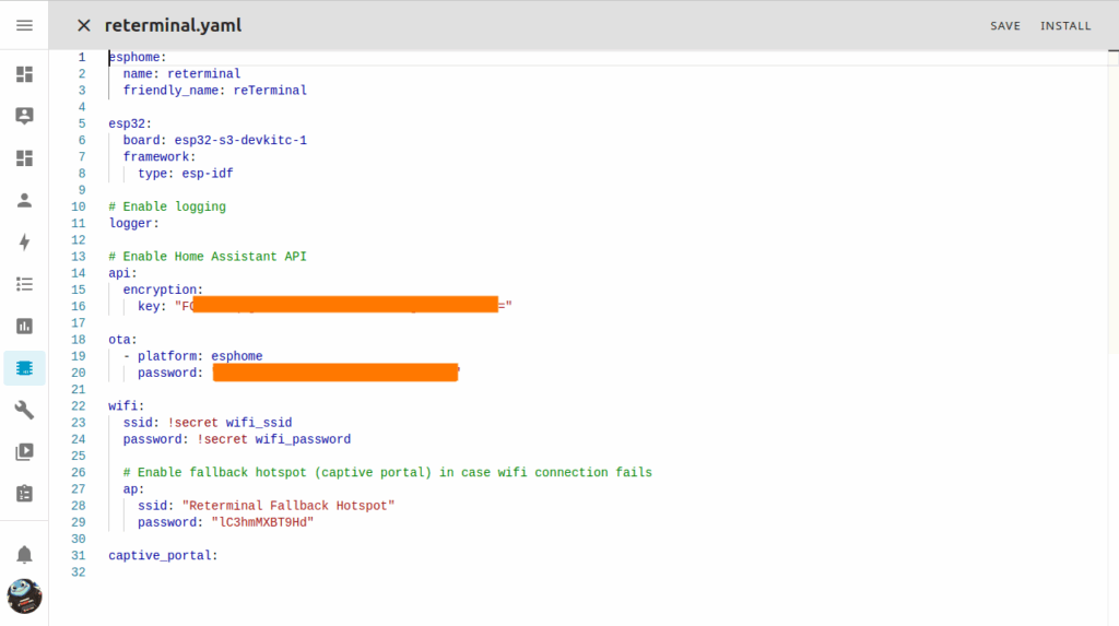
In the ESPHome Builder module, click on Edit to modify the YAML configuration so that the reTerminal displays our message.
The reTerminal E1002 screen from Seeed Studio is a 7.3-inch color E Ink® Spectra™ 6 panel with a resolution of 800×480 pixels. As you can see on the reTerminal schematic, the ESP32-S3 communicates with the screen over an SPI bus through the following pins:
- SPI Clock (CLK): GPIO 7
- Master In Slave Out (MISO): GPIO 8 (not used by the screen but only by the microSD card reader on the same SPI bus)
- Master Out Slave In (MOSI): GPIO 9
- Chip Select (CS): GPIO 10
- Data/Command (DC): GPIO 11
- Reset (RST): GPIO 12
This SPI connection is used to drive the e-paper display effectively.
Here’s the configuration that displays the message “Hello Worlds!” in blue, with the Google Inter 700 font and a size of 36 points. You can use this example by copying the code below and pasting it just after the captive_portal line in your YAML file.
captive_portal:

# define font to display words
font:
  - file: "gfonts://Inter@700"
    id: myFont
    size: 36
# define SPI interface
spi:
  clk_pin: GPIO7
  mosi_pin: GPIO9
display:
  - platform: epaper_spi
    id: epaper_display
    model: Seeed-reTerminal-E1002
    update_interval: 300s
    lambda: |-
      const auto BLUE    = Color(0,   0,   255, 0);
it.print(0, 0, id(myFont), BLUE, "Hello World!"); On an e-paper screen, it is essential to refresh the display regularly (at least once a day) to avoid the afterglow effects characteristic of this technology. In the configuration above, the display is refreshed every 300 seconds (5 minutes) via the update_interval: 300s configuration.
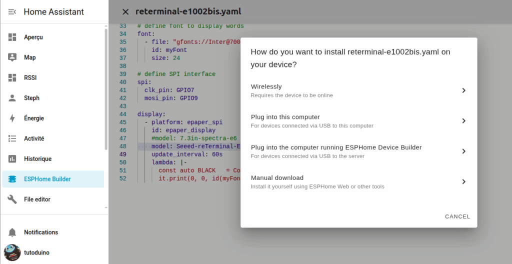
Then simply click on Install and choose the Wirelessly option to upload the firmware corresponding to this YAML configuration into the reTerminal via your Wi-Fi network (which was configured during the first upload via ESPHome).
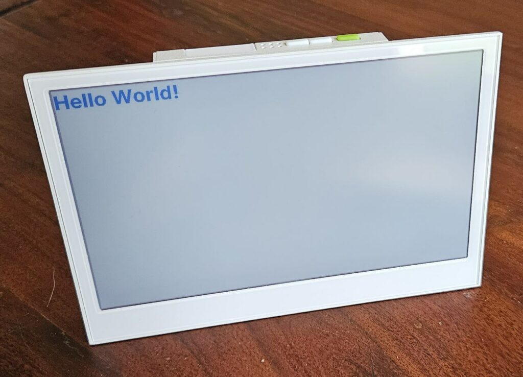
After compiling and uploading, the reTerminal displays the message Hello World! in blue on its screen.
Warning: from ESPHome version 2025.11.0 a specific configuration for reTerminal E1002 e-paper has been introduced (Refactoring #11540).
# Configuration for reTerminal E1002 display from ESPHome version 2025.11.0
# define SPI interface
spi:
  clk_pin: GPIO7
  mosi_pin: GPIO9
display:
  - platform: epaper_spi
    id: epaper_display
    model: Seeed-reTerminal-E1002
    update_interval: 300s
    lambda: |-
# Configuration for reTerminal E1002 display before ESPHome version 2025.11.0
# define SPI interface
spi:
clk_pin: GPIO7
mosi_pin: GPIO9
display:
- platform: epaper_spi
id: epaper_display
model: 7.3in-spectra-e6
cs_pin: GPIO10
dc_pin: GPIO11
reset_pin:
number: GPIO12
inverted: false
busy_pin:
number: GPIO13
inverted: true
update_interval: 300s
lambda: |-Internal temperature and humidity sensor in the reTerminal
The reTerminal has an internal temperature and humidity sensor STH40.
The ESP32-S3 communicates with this sensor via an I2C bus. Its I2C address is 0x44, and the I2C bus uses the following pins:
- Serial Data (SDA): GPIO19
- Serial Clock (SCL): GPIO20
Here is the YAML configuration that allows you to retrieve temperature and humidity from this sensor and display it on the screen, to copy just after the captive_portal line in your YAML file:
captive_portal:
# define I2C interface
i2c:
  sda: GPIO19
  scl: GPIO20
  scan: false
# temperature and humidity sensor
sensor:
  - platform: sht4x
    temperature:
      name: "Temperature"
      id: sht4x_temperature
    humidity:
      name: "Humidity"
      id: sht4x_humidity
      on_value:
        then:
          - component.update: epaper_display
    address: 0x44
    update_interval: 60s
# define font to display words
font:
  - file: "gfonts://Inter@700"
    id: myFont
    size: 36
# define SPI interface
spi:
  clk_pin: GPIO7
  mosi_pin: GPIO9
display:
  - platform: epaper_spi
    id: epaper_display
    model: Seeed-reTerminal-E1002
    update_interval: never
    lambda: |-
      const auto BLUE    = Color(0,   0,   255, 0);
      it.printf(10, 10, id(myFont), BLUE, "Temperature: %.1f°C", id(sht4x_temperature).state);
it.printf(10, 40, id(myFont), BLUE, "Humidity: %.1f%%", id(sht4x_humidity).state); It is best to refresh the screen only after the sensor reading is complete. To do this, I use the on_value parameter in the SHT4X sensor configuration. This parameter triggers the screen to refresh each time a new value is received from the sensor. Therefore, the screen’s update_interval parameter is set to never to prevent automatic, independent refresh of the sensor data.
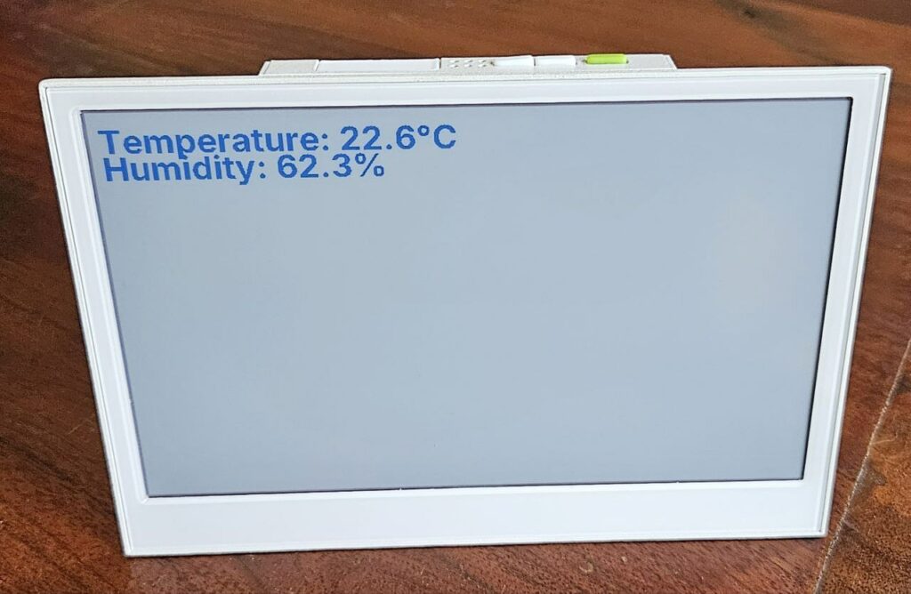
The reTerminal will display on its screen the temperature and humidity measured by its internal sensor.
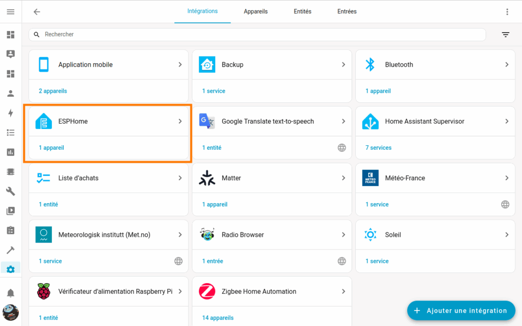
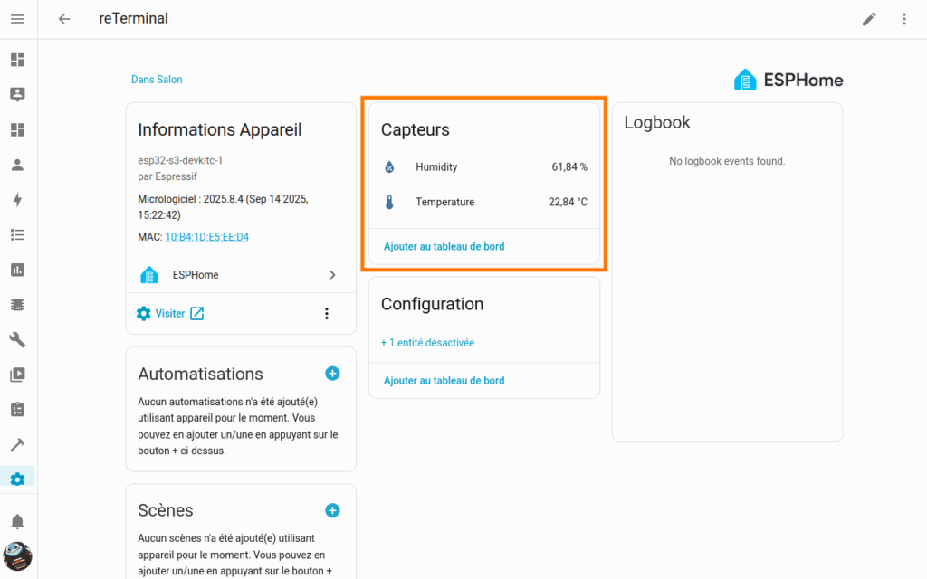
In order to access Home Assistant data, you need to add your ESPHome device integration from Parameters->Integrations menu. It should be available in the discovery section.
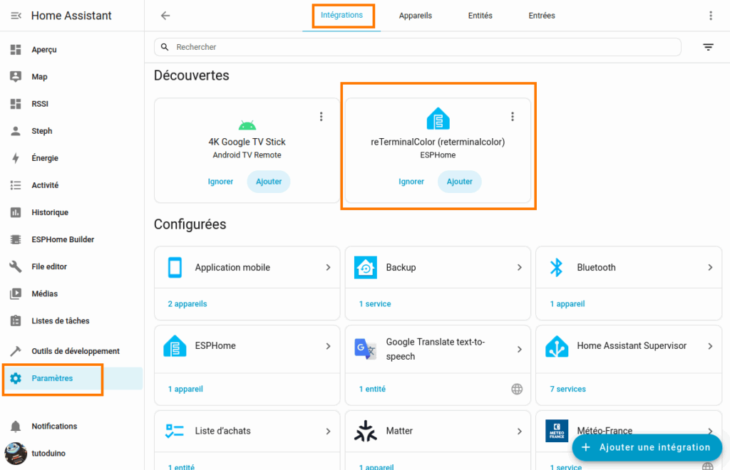
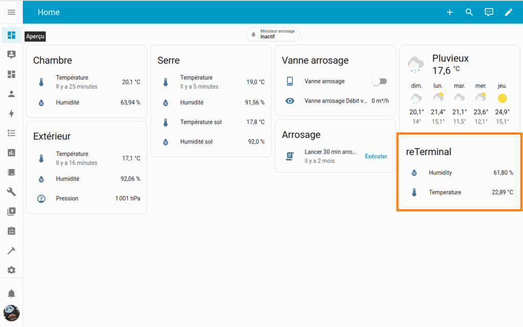
Thanks to ESPHome, it is possible to display data from reTerminal in Home Assistant.
Displaying data from an external sensor on the reTerminal screen
It is perfectly possible to display any Home Assistant entity on the reTerminal screen. As mentioned at the beginning of this tutorial, we will display on the reTerminal screen the temperature and humidity measured by the external ESP32-C6-based Zigbee sensor that I designed in my previous tutorial.
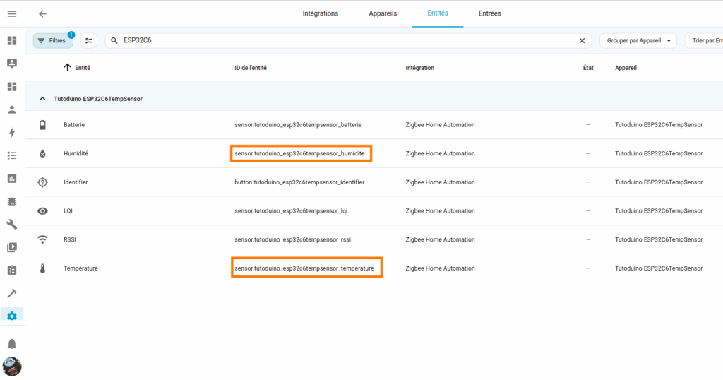
The temperature and humidity measured by this external sensor correspond to the following ID entities in Home Assistant:
- sensor.tutoduino_esp32c6tempsensor_temperature
- sensor.tutoduino_esp32c6tempsensor_humidite
Here is the code to copy just after the captive_portal line in your YAML file:
captive_portal:
# define I2C interface
i2c:
  sda: GPIO19
  scl: GPIO20
  scan: false
sensor:
  # internal temperature and humidity sensor
  - platform: sht4x
    temperature:
      name: "Temperature"
      id: sht4x_temperature
    humidity:
      name: "Humidity"
      id: sht4x_humidity
      on_value:
        then:
          - component.update: epaper_display
    address: 0x44
    update_interval: 60s
  # external EP32C6 sensor
  - platform: homeassistant
    id: tutoduino_esp32c6tempsensor_temperature
    entity_id: sensor.tutoduino_esp32c6tempsensor_temperature
  - platform: homeassistant
    id: tutoduino_esp32c6tempsensor_humidite
    entity_id: sensor.tutoduino_esp32c6tempsensor_humidite
# define font to display words
font:
  - file: "gfonts://Inter@700"
    id: myFont
    size: 36
  - file: "gfonts://Inter@700"
    id: myFontLarge
    size: 50
  - file: "gfonts://Inter@700"
    id: myFontVeryLarge
    size: 70
# define SPI interface
spi:
  clk_pin: GPIO7
  mosi_pin: GPIO9
display:
  - platform: epaper_spi
    id: epaper_display
    model: Seeed-reTerminal-E1002
    update_interval: never
    lambda: |-
      const auto BLUE = Color(0, 0, 255, 0);
      const auto GREEN = Color(0, 255, 0, 0);
      const auto BLACK = Color(0, 0, 0, 0);
      it.line(400, 0, 400, 480, BLACK);
      it.printf(130, 15, id(myFont), BLACK, "INDOOR");
      it.printf(510, 15, id(myFont), BLACK, "OUTDOOR");
      if (isnan(id(sht4x_temperature).state)) {
        it.printf(90, 120, id(myFontVeryLarge), BLUE, "--.-°C");
      } else {
        it.printf(90, 120, id(myFontVeryLarge), BLUE, "%.1f°C", id(sht4x_temperature).state);
      }
      if (isnan(id(sht4x_humidity).state)) {
        it.printf(120, 250, id(myFontLarge), BLUE, "--.-%%");
      } else {
        it.printf(120, 250, id(myFontLarge), BLUE, "%.1f%%", id(sht4x_humidity).state);
      }
      if (isnan(id(tutoduino_esp32c6tempsensor_temperature).state)) {
        it.printf(500, 120, id(myFontVeryLarge), GREEN, "--.-°C");
      } else {
        it.printf(500, 120, id(myFontVeryLarge), GREEN, "%.1f°C", id(tutoduino_esp32c6tempsensor_temperature).state);
      }
      if (isnan(id(tutoduino_esp32c6tempsensor_humidite).state)) {
        it.printf(540, 250, id(myFontLarge), GREEN, "--.-%%");
      } else {
        it.printf(540, 250, id(myFontLarge), GREEN, "%.1f%%", id(tutoduino_esp32c6tempsensor_humidite).state);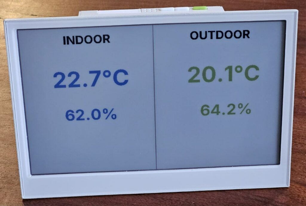
}This configuration displays data from the internal sensor in the reTerminal in the INDOOR section and data from the external sensor in the OUTDOOR section.
Display battery charge
Since my ESP32-C6 based external sensor and the reTerminal are both battery powered, it is useful to be able to display their level on the screen.
Regarding the battery level of the external sensor, it is simply retrieved via the Home Assistant entity sensor.tutoduino_esp32c6tempsensor_batterie.
To retrieve the reTerminal’s battery level, you must enable battery voltage measurement by configuring GPIO21 (VBAT ENABLE). The reading is then performed on GPIO1 (VBAT ADC), which is internally connected to the battery via a measurement circuit. By reading the analog value (voltage) on this GPIO1, it is possible to obtain an accurate estimate of the battery charge level.
Here is the configuration that allows you to retrieve the battery level and display the icons.
esphome:
  name: reterminal
  friendly_name: reTerminal
  on_boot:
    priority: 600
    then:
      - output.turn_on: bsp_battery_enable
esp32:
  board: esp32-s3-devkitc-1
  framework:
    type: esp-idf
# Enable logging
logger:
# Enable Home Assistant API
api:
  encryption:
    key: "XXXX"
ota:
  - platform: esphome
    password: "XXXX"
wifi:
  ssid: !secret wifi_ssid
  password: !secret wifi_password
  # Enable fallback hotspot (captive portal) in case wifi connection fails
  ap:
    ssid: "Reterminal Fallback Hotspot"
    password: "XXXX"
captive_portal:
output:
  - platform: gpio
    pin: GPIO21
    id: bsp_battery_enable
# define I2C interface
i2c:
  sda: GPIO19
  scl: GPIO20
  scan: false
sensor:
  # internal temperature and humidity sensor
  - platform: sht4x
    temperature:
      name: "Temperature"
      id: sht4x_temperature
    humidity:
      name: "Humidity"
      id: sht4x_humidity
    address: 0x44
    update_interval: 60s
  # external EP32C6 sensor
  - platform: homeassistant
    id: tutoduino_esp32c6tempsensor_temperature
    entity_id: sensor.tutoduino_esp32c6tempsensor_temperature
  - platform: homeassistant
    id: tutoduino_esp32c6tempsensor_humidite
    entity_id: sensor.tutoduino_esp32c6tempsensor_humidite
  - platform: homeassistant
    id: tutoduino_esp32c6tempsensor_batterie
    entity_id: sensor.tutoduino_esp32c6tempsensor_batterie
  # ADC for battery voltage measurement
  - platform: adc
    pin: GPIO1
    name: "Battery Voltage"
    id: battery_voltage
    on_value:
      then:
        - component.update: battery_level
    update_interval: 60s
    attenuation: 12db
    filters:
      - multiply: 2.0  # Voltage divider compensation
# Template to display battery level in %
  - platform: template
    name: "Battery Level"
    id: battery_level
    unit_of_measurement: "%"
    icon: "mdi:battery"
    device_class: battery
    state_class: measurement
    lambda: 'return id(battery_voltage).state;'
    update_interval: never
    filters:
      - calibrate_linear:
          - 4.15 -> 100.0
          - 3.96 -> 90.0
          - 3.91 -> 80.0
          - 3.85 -> 70.0
          - 3.80 -> 60.0
          - 3.75 -> 50.0
          - 3.68 -> 40.0
          - 3.58 -> 30.0
          - 3.49 -> 20.0
          - 3.41 -> 10.0
          - 3.30 -> 5.0
          - 3.27 -> 0.0
      - clamp:
          min_value: 0
          max_value: 100
# define font to display words
font:
  - file: "gfonts://Inter@700"
    id: mySmallFont
    size: 15
  - file: "gfonts://Inter@700"
    id: myFont
    size: 36
  - file: "gfonts://Inter@700"
    id: myFontLarge
    size: 50
  - file: "gfonts://Inter@700"
    id: myFontVeryLarge
    size: 70
  - file: 'fonts/MaterialDesignIconsDesktop.ttf'
    id: font_mdi_large
    size: 50
    glyphs:
      - "\U000F050F"  # thermometer
      - "\U000F058E"  # humidity
  - file: 'fonts/MaterialDesignIconsDesktop.ttf'
    id: font_bat_icon
    size: 50
    glyphs:
      - "\U000F0079"  # mdi-battery
# define SPI interface
spi:
  clk_pin: GPIO7
  mosi_pin: GPIO9
display:
  - platform: epaper_spi
    id: epaper_display
    model: Seeed-reTerminal-E1002
    update_interval: 60s
    lambda: |-
      const auto BLUE = Color(0, 0, 255, 0);
      const auto GREEN = Color(0, 255, 0, 0);
      const auto BLACK = Color(0, 0, 0, 0);
      const auto RED   = Color(255, 0,   0,   0);
      it.line(400, 0, 400, 480, BLACK);
      it.printf(130, 15, id(myFont), BLACK, "INDOOR");
      it.printf(510, 15, id(myFont), BLACK, "OUTDOOR");
      it.printf(60, 165, id(font_mdi_large), BLACK, TextAlign::CENTER, "\U000F050F");
      if (isnan(id(sht4x_temperature).state)) {
        it.printf(90, 120, id(myFontVeryLarge), BLUE, "--.-°C");
      } else {
        it.printf(90, 120, id(myFontVeryLarge), BLUE, "%.1f°C", id(sht4x_temperature).state);
      }
      it.printf(60, 283, id(font_mdi_large), BLACK, TextAlign::CENTER, "\U000F058E");
      if (isnan(id(sht4x_humidity).state)) {
        it.printf(90, 250, id(myFontLarge), BLUE, "--.-%%");
      } else {
        it.printf(90, 250, id(myFontLarge), BLUE, "%.1f%%", id(sht4x_humidity).state);
      }
      it.printf(60, 390, id(font_bat_icon), BLACK, TextAlign::CENTER, "\U000F0079");
      if (isnan(id(battery_level).state)) {
        it.printf(90, 360, id(myFontLarge), BLUE, "--%%");
      } else {
        it.printf(90, 360, id(myFontLarge), BLUE, "%2.0f%%", id(battery_level).state);
      }
      it.printf(470, 165 , id(font_mdi_large), BLACK, TextAlign::CENTER, "\U000F050F");
      if (isnan(id(tutoduino_esp32c6tempsensor_temperature).state)) {
        it.printf(500, 120, id(myFontVeryLarge), BLUE, "--.-°C");
      } else {
        it.printf(500, 120, id(myFontVeryLarge), BLUE, "%.1f°C", id(tutoduino_esp32c6tempsensor_temperature).state);
      }
      it.printf(470, 283, id(font_mdi_large), BLACK, TextAlign::CENTER, "\U000F058E");
      if (isnan(id(tutoduino_esp32c6tempsensor_humidite).state)) {
        it.printf(500, 250, id(myFontLarge), BLUE, "--.-%%");
      } else {
        it.printf(500, 250, id(myFontLarge), BLUE, "%.1f%%", id(tutoduino_esp32c6tempsensor_humidite).state);
      }
      it.printf(470, 390, id(font_bat_icon), BLACK, TextAlign::CENTER, "\U000F0079");
      if (isnan(id(tutoduino_esp32c6tempsensor_batterie).state)) {
        it.printf(500, 360, id(myFontLarge), BLUE, "--%%");
      } else {
        it.printf(500, 360, id(myFontLarge), BLUE, "%2.0f%%", id(tutoduino_esp32c6tempsensor_batterie).state);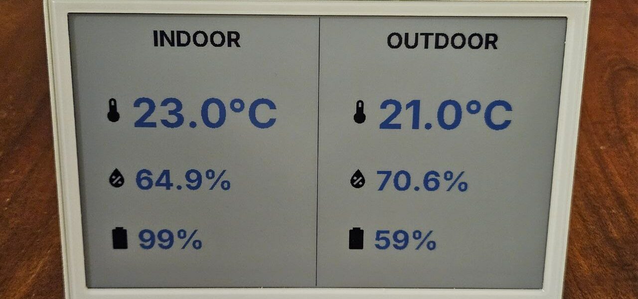
}Add icons
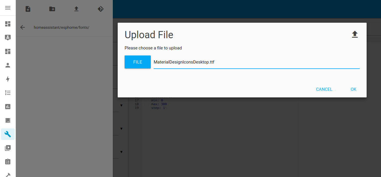
To add the thermometer, hygrometer and battery icons, you need to create the fonts directory in the esphome directory (with the module File editor)) and add the following font file to it: MaterialDesignIconsDesktop.ttf
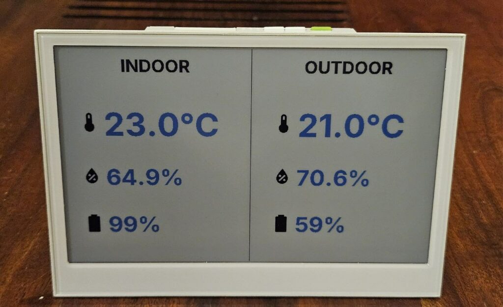
Here is how the icons appear on the reTerminal E1002 screen, but feel free to adapt them to your needs.
Sleep mode
To save the reTerminal’s battery between two screen refreshes, it’s possible to put your ESP32-S3 microcontroller into deep sleep. It’s very simple with ESPHome; simply configure the deep sleep duration using the sleep_duration parameter and the activity duration upon waking up from sleep using the run_duration parameter in the deep_sleep configuration.
To wake up the microcontroller from deep sleep, it’s possible to configure an event (timeout, pin state change, etc.). Here, I’m configuring pressing the reTerminal’s green button (GPIO3) as the event that will wake it from sleep mode.
# Deep sleep configuration to save power
deep_sleep:
  id: deep_sleep_1
  run_duration: 30s     # Active time after wake-up
  sleep_duration: 10min # Sleep duration between wake-ups
  wakeup_pin: GPIO3     # External pin to wake up device
wakeup_pin_mode: INVERT_WAKEUP # Inverted wake-up logicUpon exiting deep sleep mode, the microcontroller reboots as if it had just been powered on. This is important because it significantly impacts how sensors are read and the screen is refreshed before returning to sleep mode. Care must be taken as several potential issues arise:
- The internal SHT4X sensor is not yet ready for startup and does not return any data and thus returns nan (not a number).
- Wi-Fi is not yet initialized at startup and Home Assistant server data is not available at startup and thus returns nan.
When the sensor reading is cyclical (update_interval: 60s) this is not a problem, because this data is available during the second cycle (after 60 seconds). But it will be necessary to manage the case of a single reading at the start of the reTerminal and that the display is correct from the start.
To do this, we will perform the following actions:
1/ Reading the internal STH4X sensor and battery voltage during startup (on_boot):
  on_boot:
    priority: 600
    then:
      # Turn on the GPIO output that powers the battery measurement circuit
      - output.turn_on: bsp_battery_enable
      # Wait a short delay to allow power stabilization
      - delay: 500ms
      # Manually update battery sensors (voltage and percentage)
      - component.update: battery_voltage
      - component.update: battery_level
      # Manually read the internal temperature/humidity sensor
- component.update: sht4x_component2/ No automatic update of the internal sensor reading and battery voltage, since they are read at startup, nor automatic screen refresh.
update_interval: never # Do not update automatically (manual read only)3/ Screen refresh only when the value of the Home Assistant sensors is available (and therefore the Wi-Fi is operational):
# Home Assistant sensors (external data)
- platform: homeassistant
id: tutoduino_esp32c6tempsensor_temperature
entity_id: sensor.tutoduino_esp32c6tempsensor_temperature
on_value:
then:
# Refresh the e-paper display whenever this sensor updates
- component.update: epaper_display Here is the complete code with a 10-minute deep sleep of the reTerminal between each sensor update and screen refresh.
# ESPHome configuration for the "reterminal2" device
esphome:
name: "reterminal2" # Device name for ESPHome
friendly_name: "reterminal2" # User-friendly name for the device
  on_boot:
    priority: 600
    then:
      # Turn on the GPIO output that powers the battery measurement circuit
      - output.turn_on: bsp_battery_enable
      # Wait a short delay to allow power stabilization
      - delay: 500ms
      # Manually update battery sensors (voltage and percentage)
      - component.update: battery_voltage
      - component.update: battery_level
      # Manually read the internal temperature/humidity sensor
      - component.update: sht4x_component
# ESP32 board configuration
esp32:
board: esp32-s3-devkitc-1 # Board model
framework: # Framework settings
type: esp-idf # Use ESP-IDF framework
# Enable logging for debugging
logger:
# Home Assistant API configuration
api:
encryption: # Encryption settings for secure communication
key: "xxx=" # Encryption key
# Over-The-Air (OTA) update configuration
ota:
- platform: esphome # Use ESPHome OTA platform
password: "xxx" # OTA update password
# Wi-Fi configuration
wifi:
ssid: !secret wifi_ssid # Wi-Fi SSID (from secrets)
password: !secret wifi_password # Wi-Fi password (from secrets)
ap: # Fallback Access Point (hotspot) if Wi-Fi fails
ssid: "Re Fallback Hotspot" # Hotspot SSID
password: "xxx" # Hotspot password
captive_portal: # Enable captive portal for AP mode
# GPIO output configuration
output:
- platform: gpio # GPIO platform
pin: GPIO21 # GPIO pin number
id: bsp_battery_enable # ID for this output
# I2C bus configuration (for SHT4x sensor)
i2c:
sda: GPIO19 # I2C SDA pin
scl: GPIO20 # I2C SCL pin
scan: false # Disable automatic I2C scanning for faster boot
# Sensor configurations
sensor:
# Internal SHT4x temperature/humidity sensor
- platform: sht4x # Sensor platform
id: sht4x_component # ID for the component
temperature: # Temperature sensor
name: "Temperature" # Sensor name
id: sht4x_temperature # ID for temperature sensor
humidity: # Humidity sensor
name: "Humidity" # Sensor name
id: sht4x_humidity # ID for humidity sensor
address: 0x44 # I2C address
update_interval: never # Disable automatic updates (manual read only)
# Home Assistant sensors (external data)
- platform: homeassistant # Home Assistant sensor platform
id: tutoduino_esp32c6tempsensor_temperature # ID for this sensor
entity_id: sensor.tutoduino_esp32c6tempsensor_temperature # Home Assistant entity ID
on_value: # Action to perform when value updates
then: # List of actions
- component.update: epaper_display # Update e-paper display on value change
- platform: homeassistant # Home Assistant sensor platform
id: tutoduino_esp32c6tempsensor_humidite # ID for this sensor
entity_id: sensor.tutoduino_esp32c6tempsensor_humidite # Home Assistant entity ID
- platform: homeassistant # Home Assistant sensor platform
id: tutoduino_esp32c6tempsensor_batterie # ID for this sensor
entity_id: sensor.tutoduino_esp32c6tempsensor_batterie # Home Assistant entity ID
# ADC (analog) battery voltage measurement
- platform: adc # ADC platform
pin: GPIO1 # GPIO pin for ADC
name: "Battery Voltage" # Sensor name
id: battery_voltage # ID for this sensor
attenuation: 12db # Attenuation level
update_interval: never # Disable automatic updates (manual read only)
filters: # Data processing filters
- multiply: 2.0 # Compensate for voltage divider ratio
# Template battery level (%) derived from measured voltage
- platform: template # Template sensor platform
name: "Battery Level" # Sensor name
id: battery_level # ID for this sensor
unit_of_measurement: "%" # Unit of measurement
icon: "mdi:battery" # Icon for display
device_class: battery # Device class
state_class: measurement # State class
update_interval: never # Disable automatic updates (manual read only)
lambda: 'return id(battery_voltage).state;' # Lambda function to get voltage
filters: # Data processing filters
# Voltage-to-percentage calibration curve
- calibrate_linear: # Linear calibration
- 4.15 -> 100.0 # Voltage to percentage mapping
- 3.96 -> 90.0
- 3.91 -> 80.0
- 3.85 -> 70.0
- 3.80 -> 60.0
- 3.75 -> 50.0
- 3.68 -> 40.0
- 3.58 -> 30.0
- 3.49 -> 20.0
- 3.41 -> 10.0
- 3.30 -> 5.0
- 3.27 -> 0.0
- clamp: # Clamp values to valid range
min_value: 0 # Minimum value
max_value: 100 # Maximum value
# Deep sleep configuration to save power
deep_sleep:
id: deep_sleep_1 # ID for deep sleep component
run_duration: 30s # Time to stay awake after wake-up
sleep_duration: 10min # Time to sleep between wake-ups
wakeup_pin: GPIO3 # GPIO pin to wake up device
wakeup_pin_mode: INVERT_WAKEUP # Inverted wake-up logic
# SPI bus configuration (for the e-paper display)
spi:
clk_pin: GPIO7 # SPI CLK pin
mosi_pin: GPIO9 # SPI MOSI pin
# Font definitions for the display
font:
- file: "gfonts://Inter@700" # Google Fonts URL
id: mySmallFont # ID for this font
size: 15 # Font size
- file: "gfonts://Inter@700" # Google Fonts URL
id: myFont # ID for this font
size: 36 # Font size
- file: "gfonts://Inter@700" # Google Fonts URL
id: myFontLarge # ID for this font
size: 50 # Font size
- file: "gfonts://Inter@700" # Google Fonts URL
id: myFontVeryLarge # ID for this font
size: 70 # Font size
- file: 'fonts/MaterialDesignIconsDesktop.ttf' # Icon font file
id: font_mdi_large # ID for this font
size: 50 # Font size
glyphs: # Specific glyphs to include
- "\U000F050F" # Thermometer icon
- "\U000F058E" # Humidity icon
- file: 'fonts/MaterialDesignIconsDesktop.ttf' # Icon font file
id: font_bat_icon # ID for this font
size: 50 # Font size
glyphs: # Specific glyphs to include
- "\U000F0079" # Battery icon
# E-paper display configuration
display:
- platform: epaper_spi
id: epaper_display
model: Seeed-reTerminal-E1002
update_interval: never # Disable automatic updates
# Lambda function for drawing on the display
lambda: |-
const auto BLUE = Color(0, 0, 255, 0); # Define color constants
const auto GREEN = Color(0, 255, 0, 0);
const auto BLACK = Color(0, 0, 0, 0);
const auto RED = Color(255, 0, 0, 0);
it.line(400, 0, 400, 480, BLACK); # Draw a vertical line to separate sections
it.printf(130, 15, id(myFont), BLACK, "INDOOR"); # Print "INDOOR" label
it.printf(510, 15, id(myFont), BLACK, "OUTDOOR"); # Print "OUTDOOR" label
# Draw indoor temperature icon and value
it.printf(60, 165, id(font_mdi_large), BLACK, TextAlign::CENTER, "\U000F050F");
if (isnan(id(sht4x_temperature).state)) {
it.printf(90, 120, id(myFontVeryLarge), BLUE, "--.-°C"); # Placeholder if no data
} else {
it.printf(90, 120, id(myFontVeryLarge), BLUE, "%.1f°C", id(sht4x_temperature).state); # Display temperature
}
# Draw indoor humidity icon and value
it.printf(60, 283, id(font_mdi_large), BLACK, TextAlign::CENTER, "\U000F058E");
if (isnan(id(sht4x_humidity).state)) {
it.printf(90, 250, id(myFontLarge), BLUE, "--.-%%"); # Placeholder if no data
} else {
it.printf(90, 250, id(myFontLarge), BLUE, "%.1f%%", id(sht4x_humidity).state); # Display humidity
}
# Draw battery level icon and value
it.printf(60, 390, id(font_bat_icon), BLACK, TextAlign::CENTER, "\U000F0079");
if (isnan(id(battery_level).state)) {
it.printf(90, 360, id(myFontLarge), BLUE, "--%%"); # Placeholder if no data
} else {
it.printf(90, 360, id(myFontLarge), BLUE, "%2.0f%%", id(battery_level).state); # Display battery level
}
# Draw outdoor temperature icon and value
it.printf(470, 165 , id(font_mdi_large), BLACK, TextAlign::CENTER, "\U000F050F");
if (isnan(id(tutoduino_esp32c6tempsensor_temperature).state)) {
it.printf(500, 120, id(myFontVeryLarge), BLUE, "--.-°C"); # Placeholder if no data
} else {
it.printf(500, 120, id(myFontVeryLarge), BLUE, "%.1f°C", id(tutoduino_esp32c6tempsensor_temperature).state); # Display temperature
}
# Draw outdoor humidity icon and value
it.printf(470, 283, id(font_mdi_large), BLACK, TextAlign::CENTER, "\U000F058E");
if (isnan(id(tutoduino_esp32c6tempsensor_humidite).state)) {
it.printf(500, 250, id(myFontLarge), BLUE, "--.-%%"); # Placeholder if no data
} else {
it.printf(500, 250, id(myFontLarge), BLUE, "%.1f%%", id(tutoduino_esp32c6tempsensor_humidite).state); # Display humidity
}
# Draw outdoor battery level icon and value
it.printf(470, 390, id(font_bat_icon), BLACK, TextAlign::CENTER, "\U000F0079");
if (isnan(id(tutoduino_esp32c6tempsensor_batterie).state)) {
it.printf(500, 360, id(myFontLarge), BLUE, "--%%"); # Placeholder if no data
} else {
it.printf(500, 360, id(myFontLarge), BLUE, "%2.0f%%", id(tutoduino_esp32c6tempsensor_batterie).state); # Display battery level
}